Assembly instructions for kit #8
All rights reserved. 2001 Simple Motors, LLC ♦ www.simplemotor.com ♦
9
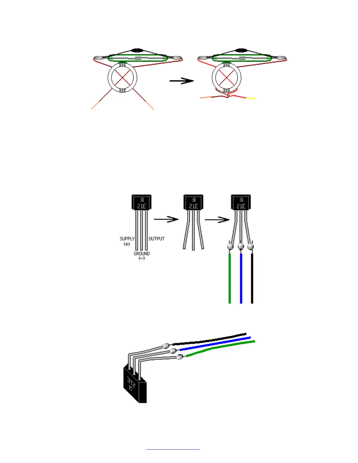
Insert the reed switch wires into the universal reed switch/Hall Effect switch stand. Be careful
not to break the reed switch, it is very fragile. Twist the wires as shown below:
21.Bend the leads of the Hall Effect switch as shown below. If your kit includes 1 large piece of
hook-up wire, cut 4 pieces with the length of 8-9" (20-23 cm) each. Strip about 3/8"
(10 mm) of insulation on each end of these wire pieces using a sharp knife. Solder three
wire pieces to the Hall Effect switch.
IMPORTANT: Do not overheat the Hall Effect switch when you solder it. The soldering iron
heat may destroy this sensitive device. If you were unable to attach the wire in 3 seconds,
let the Hall Effect IC cool off, and then try it again. Only solder one lead at a time and allow
the device to cool before soldering the next connection.
22.Bend the Hall Effect switch leads 90 degrees with branded side facing outside:


 To Next Page