4090-9116 Addressable IDNet Isolator Installation Instructions
4
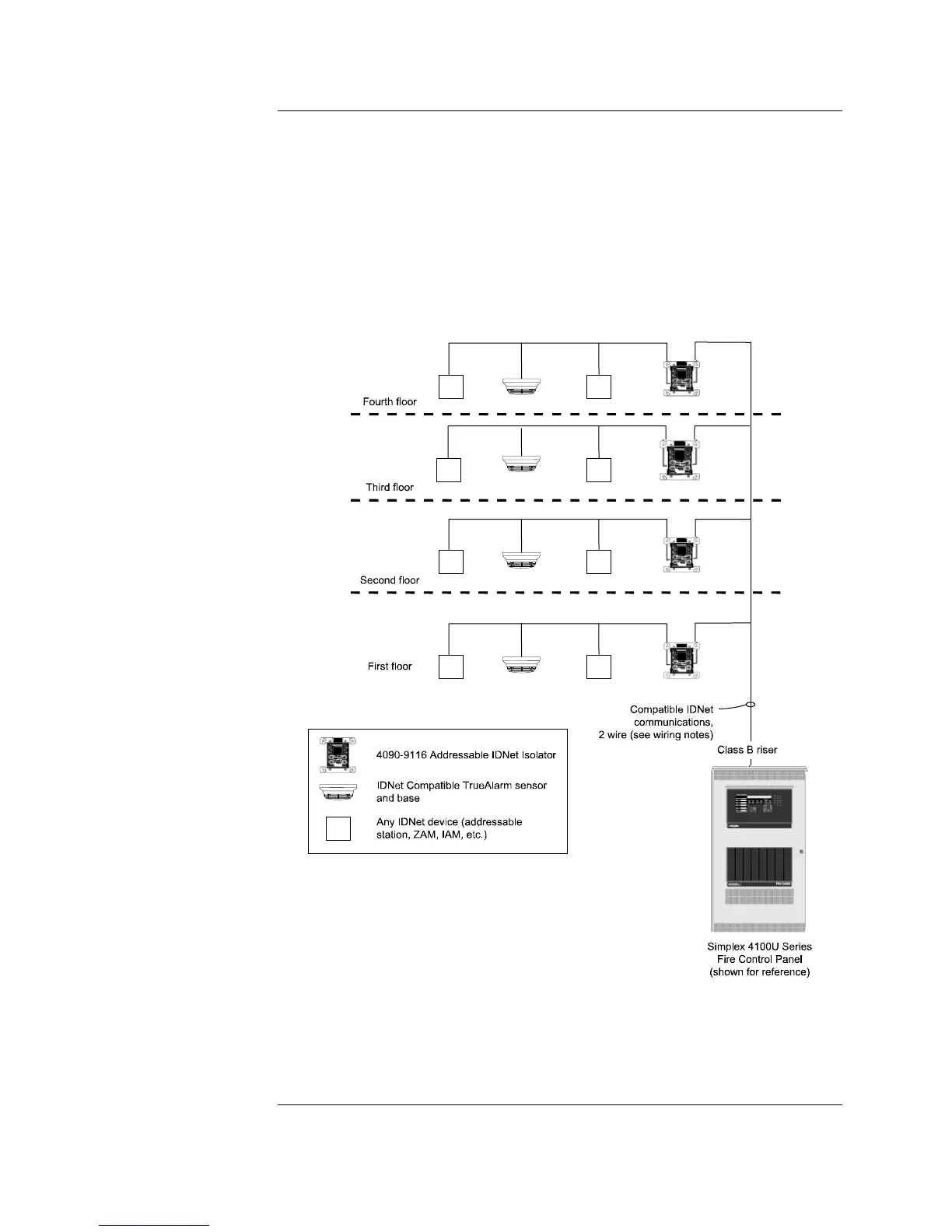
Short Circuit Isolation: The one-line diagram (figure 4) shows a multiple floor
example with Class B (style 4) IDNet communications for each floor starting at an
Isolator. If floor wiring beyond the isolator should experience a short circuit, each floor is
automatically separated from the next, preventing the short circuit from disabling the
entire IDNet communications wiring.
Earth Fault Isolation: In the event of an earth fault, each floor can be individually
isolated using built-in control panel diagnostics. With individual floor control, the earth
fault can be isolated to the floor level to narrow the search area. By adding more
isolators, the section required to be isolated can be reduced, allowing more devices to
remain active.
FD4-872-04
Figure 4. Class B Multi-Floor Wiring Example
Continued on next page
Multi-Floor Isolator
Examples
Wiring Notes:
1. Operation of the 4090-9116 Addressable IDNet
Isolator requires connection to a compatible
4100ES, 4100U, 4010ES, or 4008 IDNet communications
channel.
2. This is a one-line drawing showing only IDNet
communications wiring.
3. Some IDNet devices require additional wiring
for power. Refer to specific devices for details.
4. Maximum line resistance between panel and isolator and
between two isolators is 10 ohms (780 ft @ 18 AWG).