• Total available power is 100 W (4 A @ 25 VRMS, 1.414 A @ 70.7 VRMS).
• Terminal designations "+" and "-" are for the alarm state.
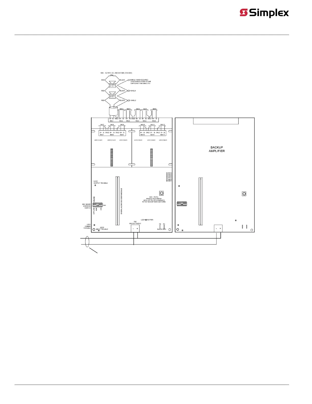
• When required, shields are normally connected to 0 V as shown. Alternate shield termination using Earth ground is provided on the amplifier
chassis.
Backup Amplifier Wiring
NACs DISABLED ON BACKUP
AMPLIFIER
See Note
TO ADDITIONAL
AMPLIFIERS FOR
ONE-FOR-MANY
CONFIGURATION
Figure 8: Backup Amplifier Wiring
Note: Backup Amplifier must be field wired as shown. Recommended wire is 12 or 14 AWG to minimize wiring losses.
• All wiring is between 18 AWG (0.8231 mm
2
) and 12 AWG (3.309 mm
2
).
• Backup audio wiring is power-limited.
• Backup audio wiring is unsupervised.
• All Amplifiers connected to the backup amplifier are in the same cabinet as the backup amplifier, or in an adjacent, close-linked cabinet.
page 11 579-174 Rev. Q
Digital/Analog Amplifiers Installation Instructions