Amplifier Specifications
Digital and Analog Amplifiers
The specifications below apply to both analog and digital amplifiers.
Input voltage: 120 VAC, 60 Hz, 4A (US and Canadian Versions)
Input: 220/230/240 VAC, 50 Hz/60 Hz, 2A
DC supply capacity: 20.4-33 VDC, 0-9.57 A load, 2 V p-p ripple (max.)
Table 1: Amplifier Battery Current Draw
Amplifier Status Average Current Draw Peak dc Current Draw
Slow Whoop 4.7 A 6.0 A
Temporal Coded Horn* 3.8 A* 10 A
Horn 9.6 A 10 A
Chime 1.8 A 6.0 A
Alarm State
Local Tone Generator (500 Hz
Square wave)
3.5 A 9.0 A
Standby, power stage supervised 400 mA (Analog amplifier) 220 mA (Digital amplifier) N/A
Standby, power stage in low power mode 75 mA N/A
* Tone used for backup battery calculations (average current draw).
The equipment operates normally with ambient temperatures outside the cabinet from 32 °F to 120 °F (0 °C to 49 °C), inclusive.
The equipment operates normally under non-condensing humidity conditions up to 93% relative humidity at 90 °F (32 °C).
Setting the Baud Rate and Address
Overview
This section describes how to configure the amplifier's baud rate and address using DIP switch SW1. Configuration is the same for analog and digital
amplifiers.
Using DIP Switch SW1
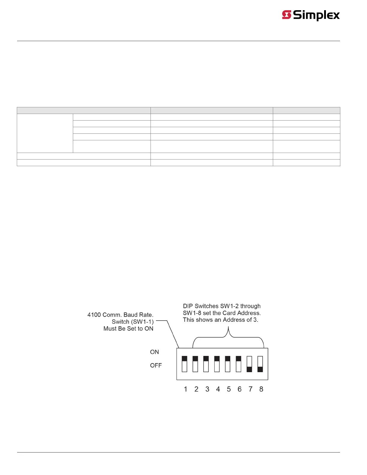
The device baud rate and address is set via DIP switch SW1, which is a bank of eight switches. From left to right (see Figure 2, below) these switches are
designated as SW1-1 through SW1-8. SW1-8 is least significant bit. The function of these switches is as follows:
• SW1-1. This switch sets the baud rate for the internal FACU communications line running between the card and the FACU CPU. Set this switch
to ON.
• SW1-2 through SW1-8. These switches set the card's address within the FACU. Refer to Figure 3 for a complete list of the switch settings for all
of the possible card addresses.
Note:
• You must set these switches to the value assigned to the card by the Programmer.
• The SW1 setting applies to audio controller slaves, including audio input cards.
Figure 2: DIP Switch SW1
page 4 579-174 Rev. Q
Digital/Analog Amplifiers Installation Instructions