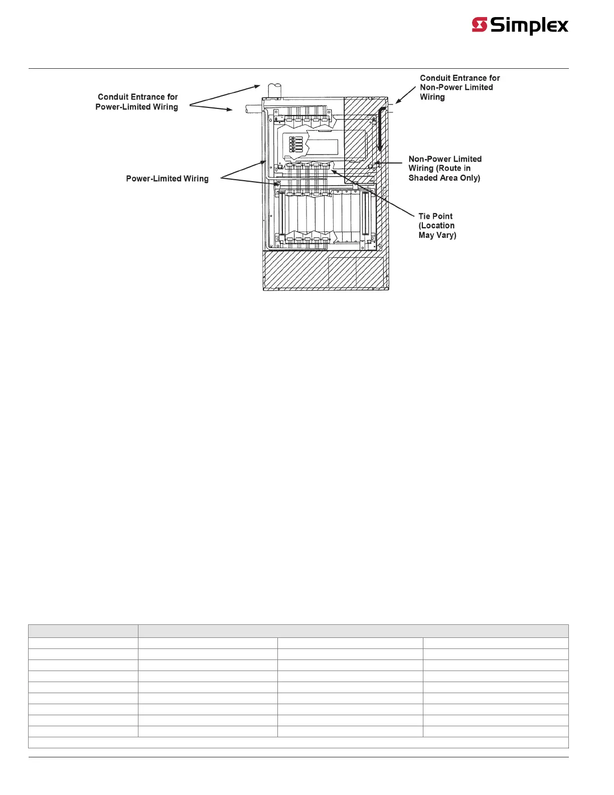
Figure 7: Non-Power Limited/Power-Limited Wiring Locations
Wiring Class A Circuits
Class A Guidelines
• Class A wiring requires purchase of 4100-5124 Class A Adapter Module
• Only TrueAlert appliances and accessories ("devices") are allowed on these signaling line circuit (SLC) channels. Refer to Table 4 for a list of
compatible TrueAlert devices and to the TrueAlert device installation instructions for connection details.
• Maximum of 63 devices or 75 unit loads per channel. Refer to section "Compatible TrueAlert Devices" for unit load ratings of TrueAlert
compatible devices. The maximum number of visuals that can be synchronized on one circuit is 43 for fixed candela and 46 for multi-candela
devices. The maximum resistance between any two visuals is 30 Ohms.
• All wiring is supervised and power limited.
• All wiring to be twisted pair. Wire must be minimum of 18 AWG (0.82 mm²) and maximum 12 AWG (3.31 mm²). If shielded pair is used, then the
cable shield drain wire must be attached back to the (–) Terminal at both Class A and Class B ends of this circuit. Only one wire per terminal
position.
• Maximum alarm current is 3.0 A per SLC channel. Use alarm current for lowest rated appliance nameplate voltage. Total alarm current for all 3
channels plus all current draw from AUX power and option cards must not exceed 9 A.
• Supervisory current is 0.20 mA per unit load.
• Maximum length of all wire segments added together is 10,000 feet (3,048 m) per channel. Maximum wire length from panel to any device is
2,500 feet (762 m).
• T-Tapping is NOT allowed. Maximum wire distance from panel to appliance farthest from the panel is the smaller of the values obtained from
Table 4 and Table 5. Add the alarm loads of all the devices on an SLC wire loop and apply to Table 4.
• Voltage rating is 24 VDC nominal, 2 V peak-to-peak ripple, maximum.
• Overvoltage suppressors are required when wiring leaves the building. Use Simplex Model 2081-9028 for wire distances of up to 1,000 feet
(305 m). Use Simplex Model 2081-9044 for long wire distances and light alarm loads. Note that the 6 Ohm line resistance of Simplex Model
2081-9044 will decrease the distances given in Table 4. Maximum two suppressors between any device and SLC channel terminals (A or B). See
General Wiring Guidelines for information regarding wiring that leaves a building.
The table below shows the maximum SLC wire lengths based on wire gauge and appliance current load.
Table 4: Maximum SLC Wire Length to Farthest Appliance Based on Appliance Current Load
Distance in Feet (Meters) to the Last Appliance
Alarm Current 18 AWG (0.82 mm2) 14 AWG (2.08 mm²) 12 AWG (3.31 mm²)
0.11 A 638 ft (194 m) 1,614 ft (492 m) 2,500 ft (762 m)
0.25 A 281 ft (86 m) 710 ft (216 m) 1,129 ft (344 m)
0.60 A 117 ft (36 m) 296 ft (90 m) 471 ft (144 m)
0.80 A 88 ft (27 m) 222 ft (68 m) 353 ft (108 m)
1.0 A 70 ft (21 m) 178 ft (54 m) 282 ft (86 m)
1.3 A ― 137 ft (42 m) 217 ft (66 m)
2.2 A ― 81 ft (25 m) 128 ft (39 m)
3.0 A ― ― 113 ft (34 m)
Distances based on 2.0 V line drop
page 11 579-336 Rev. M
4100-5120, 4100-5121, 4100-5122 TrueAlert Power Supply Installation Instructions
 Loading...