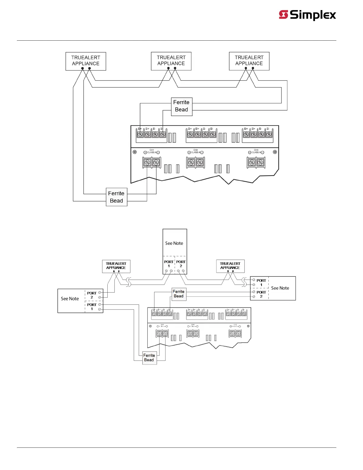
Class A Wiring Diagram (No Isolators)
Figure 8: Class A Wiring, No Isolators
Class A Wiring Diagram (With Isolators)
Figure 9: Class A Wiring, with Isolators
Note: 4905-9929 isolator.
Wiring Class B Circuits
Class B Guidelines
• Only TrueAlert appliances and accessories ("Devices") are allowed on these SLCs. Refer toTable 3 for a list of compatible TrueAlert devices and
to the TrueAlert Device Installation Instructions for connection details.
• Maximum 63 devices or 75 unit loads per channel, whichever comes first. See section "Compatible TrueAlert Devices" for unit load details. The
maximum number of visuals that can be synchronized on one circuit is 43 for fixed candela and 46 for multi-candela devices. The maximum
resistance between any two visuals is 30 Ohms.
page 13 579-336 Rev. M
4100-5120, 4100-5121, 4100-5122 TrueAlert Power Supply Installation Instructions