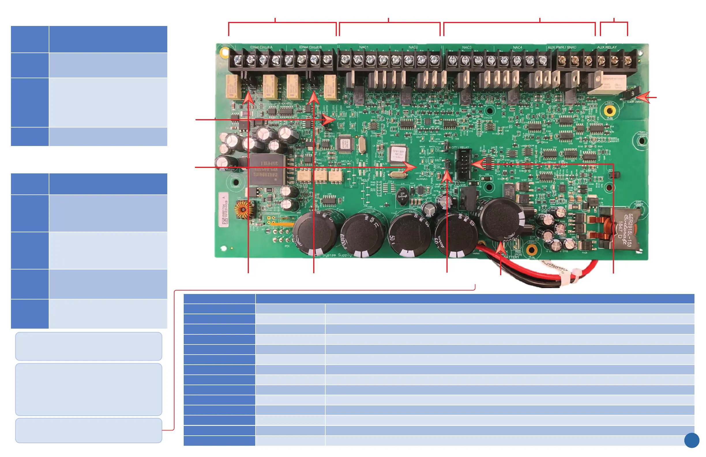
and Form C Programmable Aux Relay
P1
P3
P2 P7
TB1 TB2 TB3 TB4
LED
1- 6
LED
7 - 14
Battery Connections
Optional City
or Relay Card
Terminal
Block
and Switch
TB1
Single Channel, Dual Loop IDNet+ Circuit
which is electrically isolated and has
TB4
TB2 & TB3
These circuits are rated for Special
for more details.)
Descrip�on
P Connector
and Switch
P1
CLASS B (Note 1)
CLASS A, X
P2
CLASS B (Note 1)
CLASS A, X
P3
EARTH DETECT (Note 2)
ENABLE / DISABLE
P7
LOW BATTERY DISCONNECT
DISABLE (DOMESTIC) ENABLE (CANADA)
P Connector & Switch
LED 1
LED 2
LED 3
LED 4
IDNet POS. EARTH
IDNet COMMS
IDNet NEG. EARTH
ON = IDNet POS. EARTH
ON = COMMS LOSS
ON = IDNet NEG. EARTH
LED 5
LED 6
LED 7
LED 8
GENERAL POWER TRBL
ON = CLASS A / OPEN TRBL
ON = COMM LOSS
ON = CLASS A / OPEN TRBL
LED 9
LED 10
LED 11
LED 12
NAC 4
NAC 1
NAC 3
NAC 2
NAC 4 TRBL OR NAC 4 “ON”
NAC 1 TRBL OR NAC 1 “ON”
NAC 3 TRBL OR NAC 3 “ON”
NAC 2 TRBL OR NAC 2 “ON”
Descrip�on
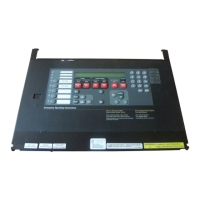
SIMPLEX 4010ES with MSS2 Main Board
Note 1: When jumpers are set for Class B on IDNet, you may
use both the B-side and the A-side to wire devices.
Thus, for Circuit B, you can have two pairs of wires per side or
four branches per circuit.
Note 2: Only one power module should be set for earth fault
Normally, the MSS2 is set to monitor for earth faults. The earth
(XBC) may also be set to monitor for earth faults. If the XBC is
50 Ah in the two-bay box.
LED 13
LED 14 AC POWER
ON = MSS2 POWER FROM AC MAIN
3
 Loading...