Field Wiring
Specifications
Step 3: Wiring the MX Digital Loop Card to Addressable Devices
The eld wiring of the MX Digital Loop Card shall follow the specications below:
• Maximum devices per loop: 250
• MX device addresses allowed: 1 to 250
• Wire Size: 12 - 18 AWG (3.31 - 0.82 mm
2
)
• 2000m cable length
• Maximum resistance: 150 ohms, Maximum Capacitance: 0.2 uF, Inductance 1.5 mH
• Shield terminates at the loop card only (if used)
• Maximum voltage: 40V
• Maximum current: 500mA peak
• Ground fault detection: 10K
• All loop wiring is supervised
Note: “T” tapped wiring is permitted as long as the overall wiring complies with the
previously mentioned inductance, capacitance, and resistance parameters and all devices
on the spur map to the same zone.
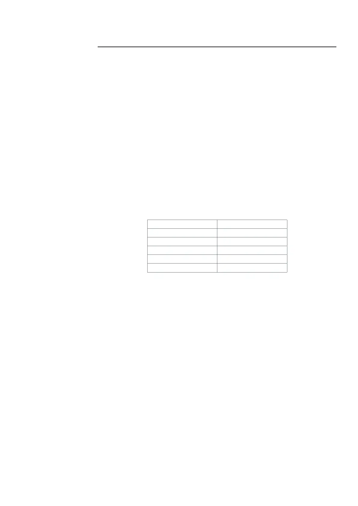
Table 3. MX Loop Terminal Block Pin out
Pins Description
TB770-1 Left +
TB770-2 Left -
TB770-3 Shield (earth)
TB770-4 Right +
TB770-5 Right -
LT0638 Iss 1.1 7/2017 8