fer, the circuit from terminal SP through the OP.
POWER TROUBLE lamp is broken and the OP.
POWER TROUBLE lamp goes out.
sistor R3 and the rectifier which causes the Son-
alert to sound (“ring-back”).
Simultaneously, 120VAC from terminal SP flows
through the transferred contacts Kl A (l&3), the
NORMAL/SILENCE switch SILENCE position, re-
sistor R4 and the rectifier which causes the Son-
alert to sound (“ring-back”). The “ring-back”
feature insures that the NORMAL/SILENCE
switch will be in the NORMAL position during
normal operation.
The Sonalert can be silenced by placing the
switch in the NORMAL position.
ZONE CIRCUIT
Normal Operation
The Sonalert can be silenced by placing the
switch in the NORMAL position.
During normal operation, -24VDC from the rec-
tifier is applied to zone terminal -24VDC. From
terminal -24VDC the current flow splits into two
paths.
Supervisory Power Failure
If the Supervisory Power fails, relay K4 de-
energizes and its contacts transfer. When the K4A
contacts transfer, 120VAC from terminal OP is
applied through the K4A contacts and terminal
EL5 to the NORMAL/SILENCE switch NORMAL
position where the current flow splits into two
paths.
One path is through resistor RI, terminal 8, the
ZONE ALARM lamp (dimly illuminating the lamp)
to terminal +24.
Resistor Rl limits current
through the ZONE ALARM lamp so that the fil-
ament glows dimly.
This permits visual monitor-
ing of the lamp filament.
The other path depends on w
ether the alarm in-
l-b
itiating devices are connected b the two-wire or
the four-wire method.
One path is through the SUP. POWER TROU-
BLE lamp (illuminating the lamp) to terminal
NEUT.
The other path is through the NORMAL/SI-
LENCE switch, resistor R3 and the rectifier (which
causes the Sonalert to sound) to terminal NEUT.
Resistor R3 is used to drop the line voltage (120
VAC) to the operating range of the Sonalert (6 to
28VDC).
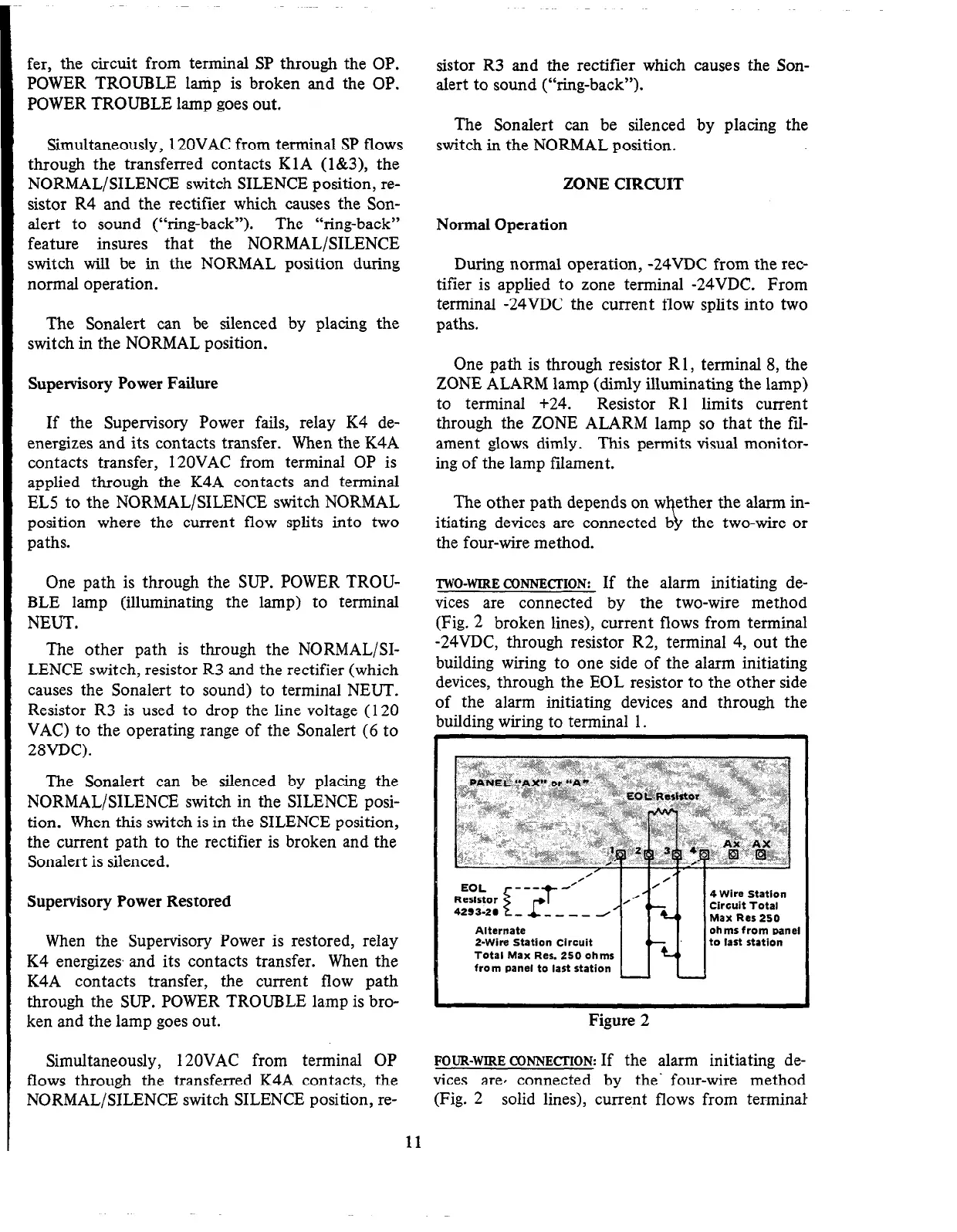
TWO-~IRE~~NNE~~ION:
If the alarm initiating de-
vices are connected by the two-wire method
(Fig. 2 broken lines), current flows from terminal
-24VDC, through resistor R2, terminal 4, out the
building wiring to one side of the alarm initiating
devices, through the EOL resistor to the other side
of the alarm initiating devices and through the
building wiring to terminal 1.
The Sonalert can be silenced by placing the
NORMAL/SILENCE switch in the SILENCE posi-
tion. When this switch is in the SILENCE position,
the current path to the rectifier is broken and the
Sonalert is silenced.
Supervisory Power Restored
When the Supervisory Power is restored, relay
K4 energizes, and its contacts transfer. When the
K4A contacts transfer, the current flow path
through the SUP. POWER TROUBLE lamp is bro-
ken and the lamp goes out.
Alternate
2-Wire Station Circuit
Total Max Res. 250 ohms
from panel to last station
ohms from panel
to last station
Figure 2
Simultaneously,
120VAC from terminal OP
FOUR-WIRE CONNECTION:
If the alarm initiating de-
flows through the transferred K4A contacts, the
vices are, connected by the‘ four-wire method
NORMAL/SILENCE switch SILENCE position, re-
(Fig. 2 solid lines), current flows from terminal
11
 Loading...


