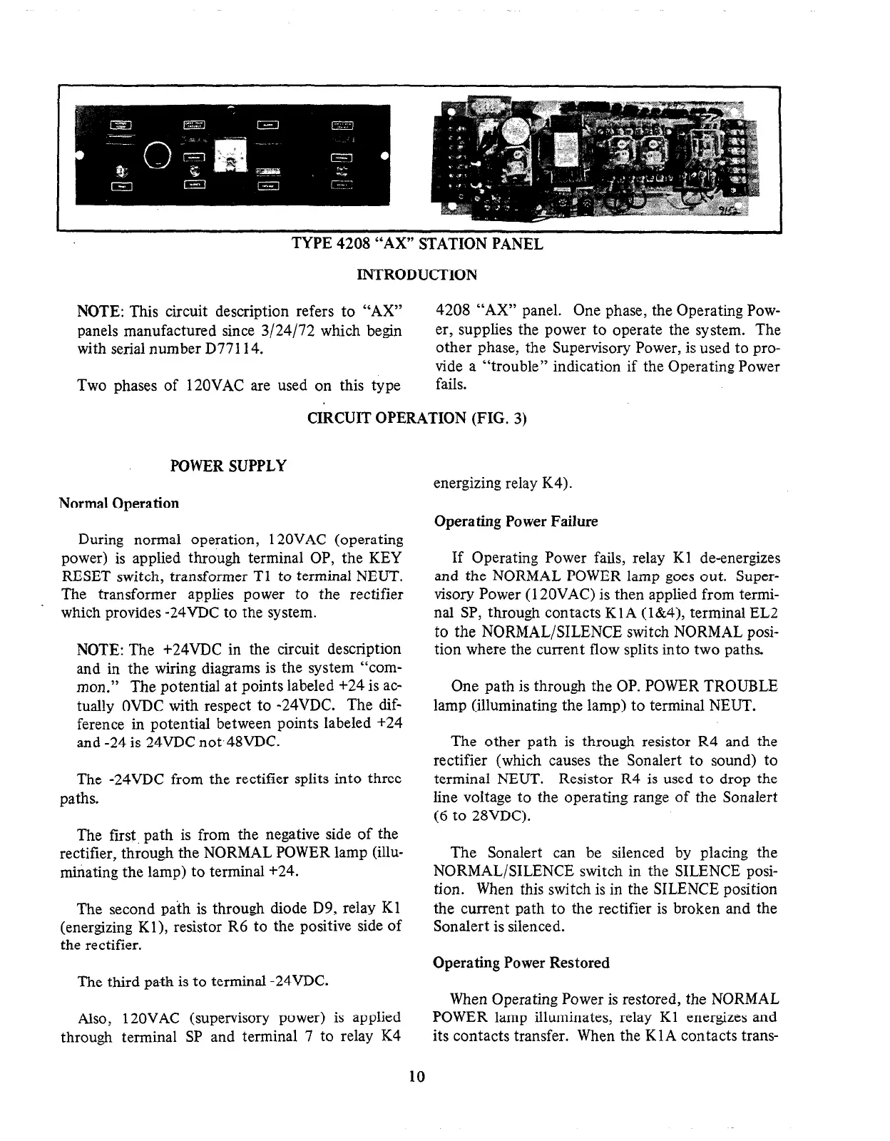
TYPE 4208 “AX” STATION PANEL
INTRODUCTION
NOTE: This circuit description refers to “AX”
4208 “AX” panel. One phase, the Operating Pow-
panels manufactured since 3/24/72 which begin
er, supplies the power to operate the system. The
with serial number D77114.
other phase, the Supervisory Power, is used to pro-
vide a “trouble” indication if the Operating Power
Two phases of 120VAC are used on this type
fails.
CIkCUIT OPERATION (FIG. 3)
POWER SUPPLY
Normal Operation
During normal operation, 120VAC (operating
power) is applied through terminal OP, the KEY
RESET switch, transformer Tl to terminal NEUT.
The transformer applies power to the rectifier
which provides -24VDC to the system.
NOTE: The +24VDC in the circuit description
and in the wiring diagrams is the system “corn-
mon.” The potential at points labeled +24 is ac-
tually OVDC with respect to -24VDC. The dif-
ference in potential between points labeled +24
and -24 is 24VDC not48VDC.
The -24VDC from the rectifier splits into three
paths.
The first, path is from the negative side of the
rectifier, through the NORMAL POWER lamp (illu-
minating the lamp) to terminal +24.
The second path is through diode D9, relay Kl
(energizing Kl), resistor R6 to the positive side of
the rectifier.
The third path is to terminal -24VDC.
Also, 120VAC (supervisory power) is applied
through terminal SP and terminal 7 to relay K4
energizing relay K4).
Operating Power Failure
If Operating Power fails, relay Kl de-energizes
and the NORMAL POWER lamp goes out. Super-
visory Power (120VAC) is then applied from termi-
nal SP, through contacts Kl A (l&4), terminal EL2
to the NORMAL/SILENCE switch NORMAL posi-
tion where the current flow splits into two paths.
One path is through the OP. POWER TROUBLE
lamp (illuminating the lamp) to terminal NEUT.
The other path is through resistor R4 and the
rectifier (which causes the Sonalert to sound) to
terminal NEUT. Resistor R4 is used to drop the
line voltage to the operating range of the Sonalert
(6 to 28VDC).
The Sonalert can be silenced by placing the
NORMAL/SILENCE switch in the SILENCE posi-
tion. When this switch is in the SILENCE position
the current path to the rectifier is broken and the
Sonalert is silenced.
Operating Power Restored
When Operating Power is restored, the NORMAL
POWER lamp illuminates, relay Kl energizes and
its contacts transfer. When the KlA contacts trans-
10
 Loading...


