contacts make and shunt out the EOL resistor R5.
With the EOL resistor out of the circuit, alarm
relay K3 energizes and its contacts transfer. When
the K3A contacts transfer they apply -24VDC
from terminal -24VDC through K3A (l&3) to:
(1) illuminate the particular zone ALARM lamp,
(2) activate the alarm signaling devices and, (3)
latch relay K3.
The zone ALARM lamp illuminates brightly
when current flows through diode D3, terminal 8,
the ALARM lamp to terminal +BAT.
The alarm signaling devices sound when current
flows through diode D2 and out terminal 7 to the
signal panel.
Current flows through diode Dl, terminal 1, re-
lays K2 and K3 to terminal +BAT to latch relay K3.
NOTE: Diode Dl is removed for coded operation
Contacts K3B are used for auxiliary purposes.
Reset Circuit
The KEY RESET switch is used to silence the
alarm signaling devices and to restore the “A” panel
to normal operation after an alarm. Turning the
KEY RESET switch 60 degrees clockwise breaks
the holding circuit for relays K2 and K3 and causes
them to de-energize. The “A” panel operation is
identical to a Zone Trouble Condition operation. (
After the alarm initiating device contacts have
been reset, the KEY RESET switch must be retum-
ed to the normal (vertical) position.
When the
KEY RESET switch is returned to the normal posi-
tion the “A” panel resumes normal operation and
the Sonalert sounds (“ring-back”). Refer to “A”
Panel - Trouble Repaired for detailed circuit des-
cription.
and relay K3 does not latch.
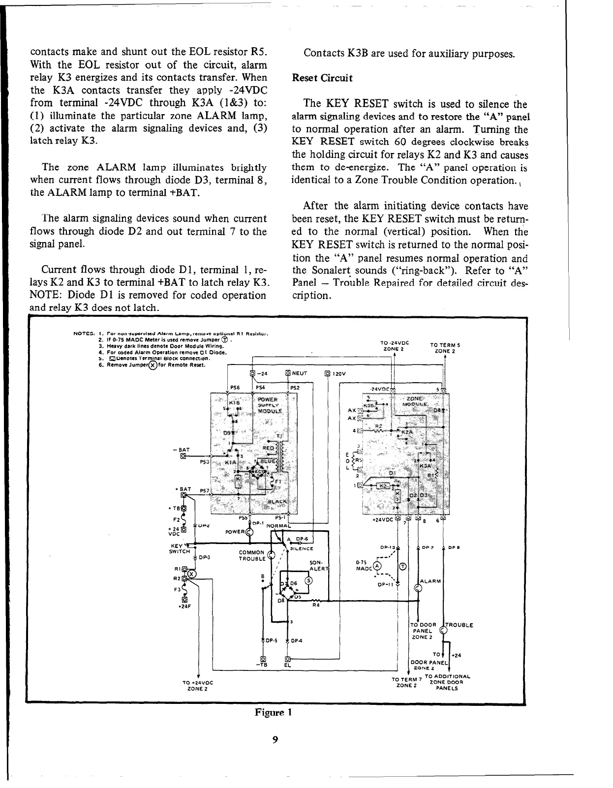
NOTES: I. For nonamervised Alarm Lamp, remove optional Rt Rerirtor.
2. If O-75 MADC Meter is used remove Jumper @
3. Heavy dark lines denote Door Module Wiring.
TO -24VDC
TO TERM 5
4. Far coded Alarm Operation remove OI Diode.
ZONE 2
ZONE 2
5. q Dsnoter Terminal Block connection.
6. Remove Jumper@for Remote Reset.
r
r
I
!I
J
I
KEY vt;
I
ZO”
i!
II
TO ADDITIONAL
TO l 24voc
TO TERM 7
ZONE 2
ZONE DOOR
ZONE Z
PANELS
Figure 1