-m-w-/
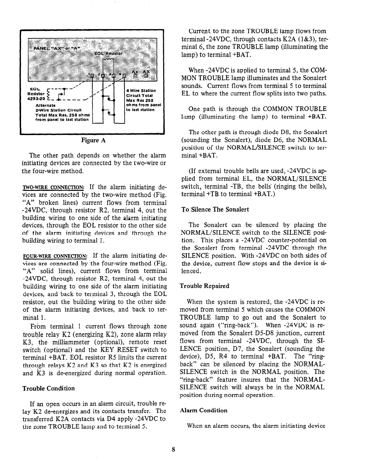
Alternate
2aWire Station Circuit
Total Max Res. 250 ohms
from panel to last station
4 Wire Station
Circuit Total
Max Res 250
ohms from panel
to last station
Figure
A
The other path depends on whether the alarm
initiating devices are connected by the two-wire or
the four-wire method.
TWO-WIRE CONNECTION:
If the alarm initiating de-
vices are connected by the two-wire method (Fig.
“A” broken lines) current flows from terminal
-24VDC, through resistor R2, terminal 4, out the
building wiring to one side of the alarm initiating
devices, through the EOL resistor to the other side
of the alarm initiating devices and through the
building wiring to terminal 1.
FOUR-WIRE CoNNEcrION:
If the alarm initiating de-
vices ‘are connected by the four-wire method (Fig.
“A” solid lines), current flows from terminal
-24VDC, through resistor R2, terminal 4, out the
building wiring to one side of the alarm initiating
devices, and back to terminal 3, through the EOL
resistor, out the building wiring to the other side
of the alarm initiating devices, and back to ter-
minal 1.
From terminal 1 current flows through zone
trouble relay K2 (energizing K2), zone alarm relay
K3, the milliammeter (optional), remote reset
switch (optional) and the KEY RESET switch to
terminal +BAT. EOL resistor R5 limits the current
through relays .K2 and K3 so that K2 is energized
and K3 is de-energized during normal operation.
Trouble Condition
If an open occurs in an alarm circuit, trouble re-
lay K2 de-energizes and its contacts transfer. The
transferred K2A contacts via D4 apply -24VDC to
the zone TROUBLE lamp and to terminal 5.
Current. to the zone TROUBLE lamp flows from
terminal -24VDC, through contacts K2A (l&3), ter-
minal 6, the zone TROUBLE lamp (illuminating the
lamp) to terminal +BAT.
When -24VDC is applied to terminal 5, the COM-
MON TROUBLE lamp illuminates and the Sonalert
sounds. Current flows from terminal 5 to terminal
EL to where the current flow splits into two paths.
One path is through the COMMON TROUBLE
limp (illuminating the lamp) to terminal +BAT.
The other path is through diode D8, the Sonalert
(sounding the Sonalert), diode D6, the NORMAL
position of the NORMAL/SILENCE switch to ter-
minal +BAT.
(If external trouble bells are used, -24VDC is ap-
plied from terminal EL, the NORMAL/SILENCE
switch, terminal -TB, the bells’ (ringing the bells),
terminal +TB to terminal +BAT.)
To Silence The Sonalert
The Sonalert can be silenced by placing the
NORMAL/SILENCE switch to the SILENCE posi-
tion. This places
a
-24VDC counter-potential on
the Sonalert from terminal -24VDC through the
SILENCE position. With -24VDC on both sides of
the device, current flow stops and the device is si-
lenced.
Trouble Repaired
When the system is restored, the -24VDC is re-
moved from terminal 5 which causes the COMMON
TROUBLE lamp to go out and the Sonalert to
sound again (“ring-back”). When -24VDC is re-
moved from the Sonalert D5-D8 junction, current
flows from terminal -24VDC, through the SI-
LENCE position, D7, the Sonalert (sounding the
device), D5, R4 to terminal +BAT. The “ring-
back” can be silenced by placing the NORMAL-
SILENCE switch in the NORMAL position. The
“ring-back” feature insures that the NORMAL-
SILENCE switch will always be in the NORMAL
position during normal operation.
Alarm Condition
When an alarm occurs, the alarm initiating device
8
 Loading...


