SERVICE INSTRUCTIONS
TYPE 4208 FIRE ALARM SYSTEMS
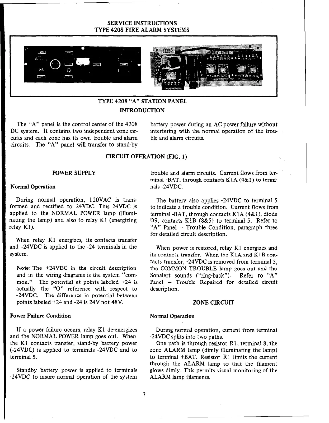
‘1’Y l’r. --A”
s’l Al‘lUN YANEL
INTRODUCTION
The “A” panel is the control center of the 4208
battery power during an AC power failure without
DC system. It contains two independent zone cir-
interfering with the normal operation of the trou- :
cuits and each zone has its own trouble and alarm
ble and alarm circuits.
circuits.
The “A” panel will transfer to stand-by
CIRCUIT OPERATION (FIG. 1)
POWER SUPPLY
Normal Operation
During normal operation, 12OVAC is trans-
formed and rectified to 24VDC. This 24VDC is
applied to the NORMAL POWER lamp (illumi-
nating the lamp) and also to relay Kl (energizing
relay Kl).
When relay Kl energizes, its contacts transfer
and -24VDC is applied to the -24 terminals in the
system.
Note: The +24VDC in the circuit description
and in the wiring diagrams is the system “com-
mon.” The potential at points labeled +24 is
actually the “0” reference with respect to
-24VDC. The difference in potential between
points labeled +24 and -24 is 24V not 48V.
Power Failure Condition
If a power failure occurs, relay Kl de-energizes
and the NORMAL POWER lamp goes out. When
the Kl contacts transfer, stand-by battery power
(-24VDC) is applied to terminals -24VDC and to
terminal 5.
Standby battery power is applied to terminals
-24VDC to insure normal operation of the system
trouble and alarm circuits. Current flows from ter-
minal -BAT. through contacts KlA (4&l) to termi-
nals -24VDC.
The battery also applies -24VDC to terminal 5
to indicate a trouble condition. Current flows from
terminal -BAT, through contacts KlA (4&l ), diode
D9, contacts KIB (8&5) to terminal 5. Refer to
“A” Panel
- Trouble Condition, paragraph three
for detailed circuit description.
When power is restored, relay Kl energizes and
its contacts transfer. When the KlA and KlB con-
tacts transfer, -24VDC is removed from terminal 5,
the COMMON TROUBLE lamp goes out and the
Sonalert sounds (“ring-back”). Refer to “A”
Panel
- Trouble Repaired for detailed circuit
description.
ZONE CIRCUIT
Normal Operation
During normal operation, current from terminal
-24VDC splits into two paths.
One path is through resistor Rl, terminal 8, the
zone ALARM lamp (dimly illuminating the lamp)
to terminal +BAT. Resistor Rl limits the current
through the ALARM lamp so that the filament
glows dimly. This permits visual monitoring of the
ALARM lamp filaments.
7
 Loading...


