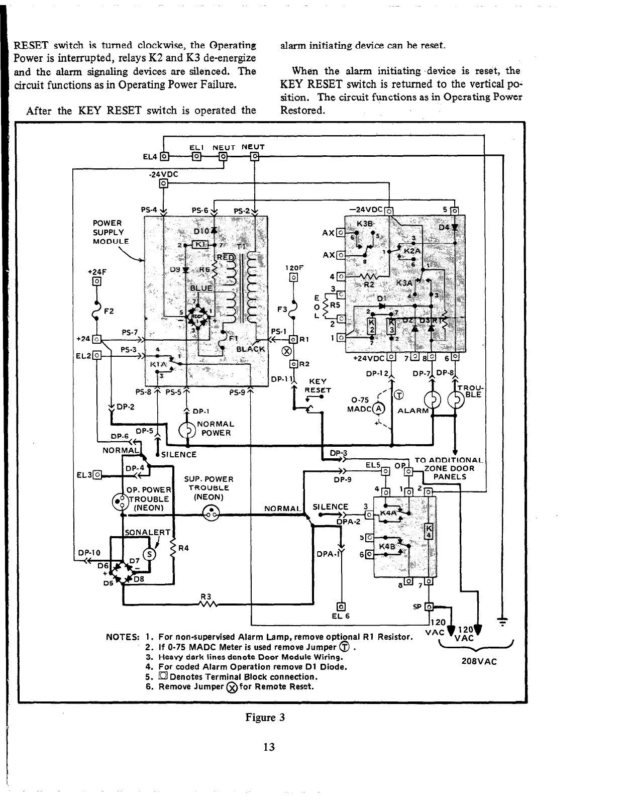
ESET switch is turned clockwise, the Operating
)wer is interrupted, relays K2 and K3 de-energize
Id the alarm signaling devices are silenced. The
rcuit functions as in Operating Power Failure.
After the KEY RESET switch is operated the
alarm initiating device can be reset.
When the alarm initiating .device is reset, the
KEY RESET switch is returned to the vertical po-
sition.
The circuit functions as in Operating Power
Restored.
EL1
NEUT NEUT
-24VDC
POWER
SUPPLY
MODULE
\
r
+24F
F2
E
0
L
EL2
IL3&m SUP. POWER
R4
( _’
x
DP-1 1
L
I-
I
R3
I
DP-1’ 1
-
‘A
KEY
RESET
l-ranl 1.
P
f
la
EL 6
SP 0
9-l
NOTES: 1. For non-supervised Alarm Lamp, remove optional Rl Resistor.
2. If O-75 MADC Meter is used remove Jumper @ .
3. Heavy dark lines denote Door Module Wiring.
4. For coded Alarm Operation remove Dl Diode.
5. a Denotes Terminal Block connection.
6. Remove Jumper @for Remote Reset.
208VAC
Figure 3
13