When the KlA contacts transfer they shunt su-
pervisory relay K3 and cause it to de-energize. The
L.E.B. is activated when the resistance of K3 is re-
moved from the line circuit. Current flows from
terminal 12, through the L.E.B. (activating the
L.E.B.), resistor Rl, contacts KlA (3&l), terminal
8 to +24VDC at terminal 11.
Also, when K3 de-energizes contacts K3B apply
-24VDC to panel “A” or “AX” terminal 5 which
causes a trouble indication on the panel. Refer to
“D” panel Trouble Condition for detailed circuit
description.
DRILL CIIkUIT
Drill Operation
When the DRILL switch is closed, drill relay K2
energizes and its contacts transfer. Current flows
from terminal 12 through relay K2 (energizing the
relay), the closed contacts of the DRILL switch,
terminals 1, 8 and 7 to +24VDC at terminal 11.
Also, the DRILL lamp illuminates when the
DRILL switch is closed. Current flows from termi-
nal 12, through terminal 2, terminal 1, the DRILL
lamp (illuminating the lamp), the closed contacts
of the DRILL switch, terminals 1, 8 and 7 to
+24VDC at terminal 11.
When contacts K2A transfer, -24VDC is applied
from terminal 15 to the signal panels to sound the
alarm signaling devices. Current flows from termi-
nal 12, through contacts K2A (l&3) and out ter-
minal 15 to the alarm signaling devices.
When contacts K2B transfer, they break the cir-
cuit through alarm relay Kl and prevent Kl from
energizing. This keeps the alarm from energizing
the municipal alarm box. Refer to “Alarm Condi-
tion” for alarm relay Kl operation.
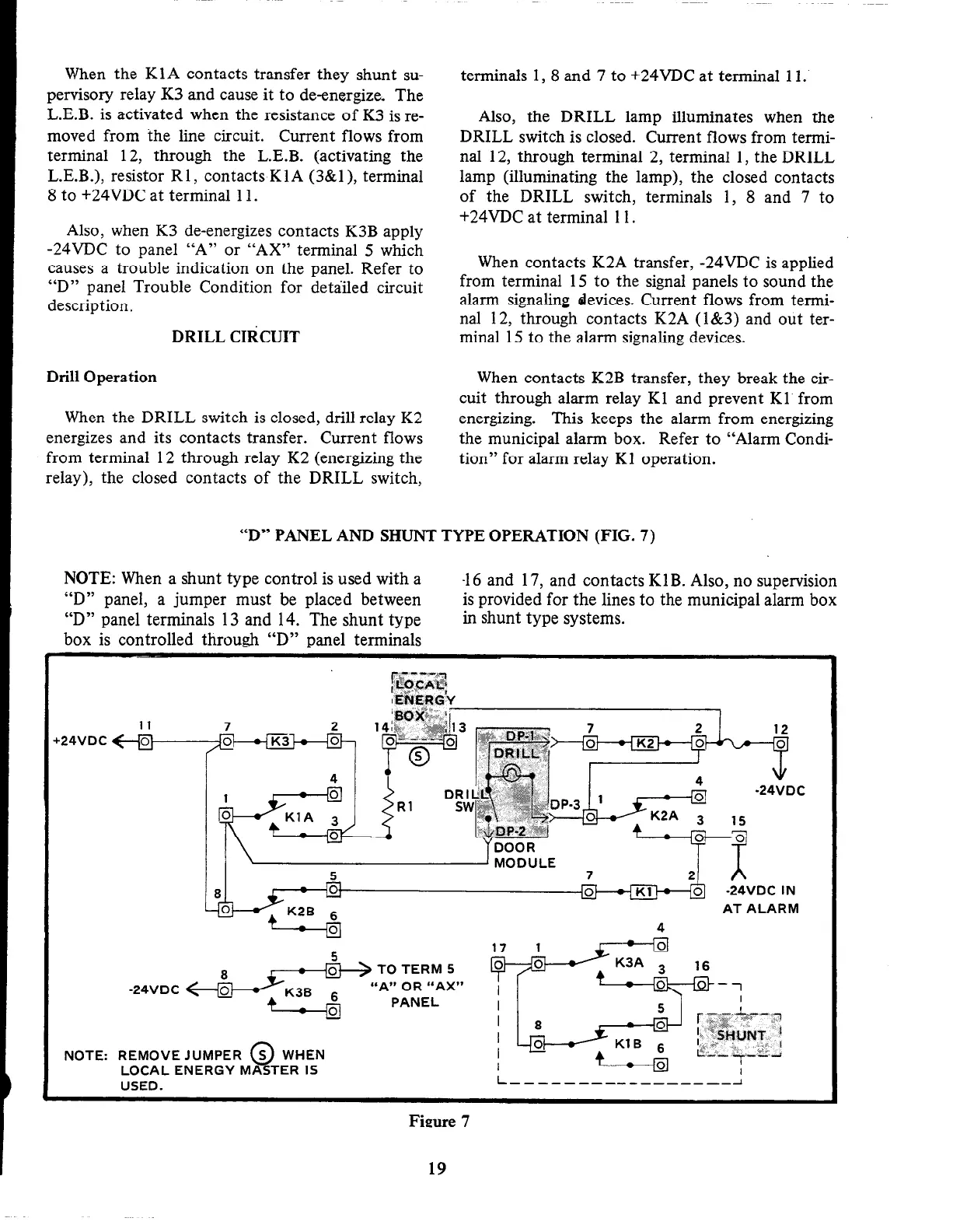
“D” PANEL AND SHUNT TYPE OPERATION (FIG. 7)
NOTE: When a shunt type control is used with a
“D” panel, a jumper must be placed between
“D” panel terminals 13 and 14. The shunt type
box is controlled through “D” panel terminals
-16 and 17, and contacts KlB. Also, no supervision
is provided for the lines to the municipal alarm box
in shunt type systems.
124VDC
NOTE:
-24VDC
REMOVE
LOCAL E
AT ALARM
4
“A” OR “AX”
JUMPER @ WHEN
NERGY MASTER IS
USED.
L------------------1
Figure 7
19