ALARM CIRCUIT
Alarm Condition
When an alarm is initiated within the 4208 sys-
tern, -24VDC is applied to “D” panel terminal 15
which energizes alarm relay K 1.
tion on the panel.
Contacts KlB transfer and interrupt the munci-
pal shunt control circuit, which causes the munci-
pal shunt control to indicate an alarm condition.
DRILL CIRCUIT
Contacts KlA (l&3) transfer which shunts trou-
ble relay K3 and causes it to de-energize. The
transferred K3B contacts apply -24VDC to “A” or
“AX” terminal 5 which causes a “trouble” indica-
Drill Operation
Identical to L.E.B. Drill Operation.
TYPE 4208 “E”
AUXILIARY RELAY PANEL
GENERAL
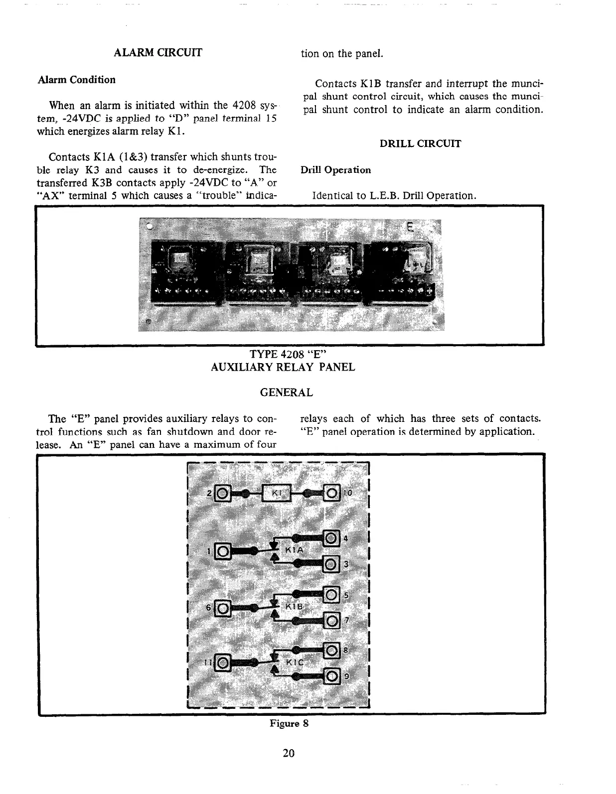
The “E” panel provides auxiliary relays to con-
trol functions such as fan shutdown and door re-
lease. An “E” panel can have a maximum of four
relays each of which has three sets of contacts.
“E” panel operation is determined by application.
Figure 8
20