2
2
2
TO TERM. 5
TO TERM. 3
TO TERM. 4
3
3
3
NOTE:
This alarm signaling device would not be supervised
if terminal 3 on the F panel was connected to
terminal 1 when an odd number of alarm signaling
devices are used.
Figure 9
tailed circuit description.)
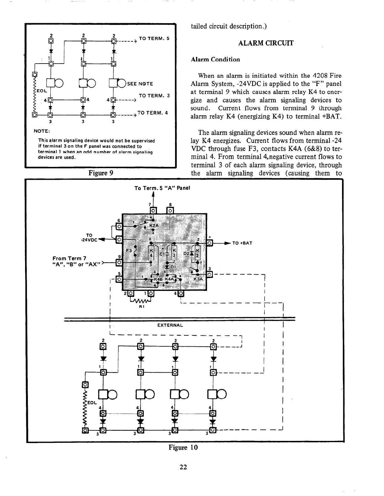
ALARM CIRCUIT
Alarm Condition
When an alarm is initiated within the 4208 Fire
Alarm System, -24VDC is applied to the “F” panel
at terminal 9 which causes alarm relay K4 to ener-
gize and causes the alarm signaling devices to
sound. Current flows from terminal 9 through
alarm relay K4 (energizing K4) to terminal +BAT.
The alarm signaling devices sound when alarm re-
lay K4 energizes. Current flows from terminal -24
VDC through fuse F3, contacts K4A (6&8) to ter-
minal 4. From terminal 4,negative current flows to
terminal 3 of each alarm signaling device, through
the alarm signaling devices (causing them to
To Term. 5 “A” Panel
TO +BAT
From Term 7
“A”, “B” or “AX”
EXTERNAL
I
L --------- ------7
I
I
I I
Figure 10