sound), the terminal l-2 diodes, terminal 5, con-
tacts K4B (l&3) to terminal +BAT.
devices is to be used, connect terminal 1 of the
first device to terminal 3 of the “F” or “G”
panel.
Simultaneously, relay K3 de-energizes when the
K4A contacts transfer. When the K3A contacts
transfer, relay K2 de-energizes and causes a “trou-
ble” condition in the “A” panel.
NOTE: When an even number of alarm signaling
I
When an
odd
‘number of alarm signaling
devices is to be used, connect terminal 4 of the
first device to terminal 3 of the “F” or “G” pan-
el. (This provides supervision to the first device.
See Fig. 9).
SUPERVISION CIRCUIT
Trouble Condition
Normal Operation
Same as “F” panel “Trouble Condition.”
During normal operation, each alarm signaling
device is supervised as current flows from terminal
-24VDC through terminal -, fuse F3, contacts K4B
(4&l), terminal 5, the building wiring, terminals 2
of the alarm signaling devices, to terminal 1 of the
last device where the current flow splits into two
paths.
ALARM CIRCUIT
Alarm Condition
One path is through the signaling devices via ter-
minals 1 and 4 to “G” panel terminal 3, the K3A
contacts, supervision relay K2 (energizing K2) to
terminal +BAT.
When an alarm occurs, -24VDC is applied to the
“G” panel at terminal 9 which energizes alarm re-
lay K4 and McCulloh relay K5 and causes the alarm
signaling devices to sound. Current flows from ter-
minal 9, through alarm relay K4 (energizing K4) to
terminal +BAT. Simultaneously, current also flows
from terminal 9, through McCulloh relay K5 (ener-
gizing K5) to terminal +BAT.
The other path is through terminal 1 of the last
device, McCulloh contacts K5A (l&4), “G” panel
terminal 2, resistor R 1, terminal 1, McCulloh con-
tacts K5B (5&8), alarm signal terminals 3, “G”
panel terminal 4, contacts K4A (8&5), diode Dl,
relay K3 (energizing K3) to terminal +BAT.
The alarm signaling devices sound when relays
K4 and K5 energize. Current flows from terminal
-24VDC, through terminal -, fuse F3, contacts K4A
(6&8) to terminal 4 where the current flow splits
into two paths.
One path is to terminal 3 of the first alarm sig-
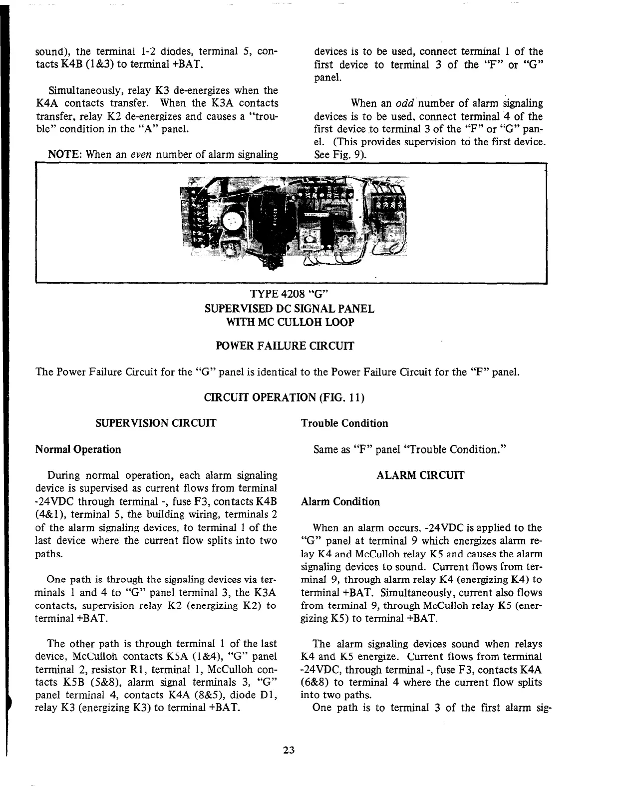
TYPE 4208 “G”
SUPERVISED DC SIGNAL PANEL
WITH MC CULLOH LOOP
POWER FAILURE CIRCUIT
The Power Failure Circuit for the “G” panel is identical to the Power Failure Circuit for the “F” panel.
CIRCUIT OPERATION (FIG. 11)
23
 Loading...


