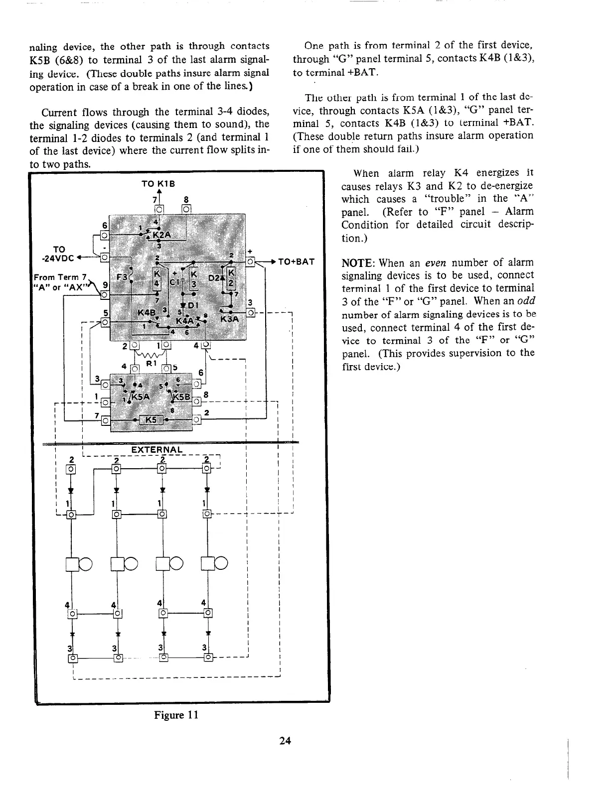
naling device, the other path is through contacts
K5B (6&8) to terminal 3 of the last alarm signal-
ing device. (These double paths insure alarm signal
operation in case of a break in one of the lines.)
Current flows through the terminal 3-4 diodes,
the signaling devices (causing them to sound), the
terminal l-2 diodes to terminals 2 (and terminal 1
of the last device) where the current flow splits in-
to two uaths.
One path is from terminal 2 of the first device,
through “G” panel terminal 5, contacts K4B (l&3),
to terminal +BAT.
The other path is from terminal 1 of the last de-
vice, through contacts K5A (l&3), “G” panel ter-
minal 5, contacts K4B (l&3) to terminal +BAT.
(These double return paths insure alarm operation
if one of them should fail.)
TO KlB
I
FYTFSNAL
EXTERNAL
I
,BAT
When alarm relay K4 energizes it
causes relays K3 and K2 to de-energize
which causes a “trouble” in the “A”
panel. (Refer to
“F” panel - Alarm
Condition for detailed circuit descrip-
tion.)
NOTE: When an even number of alarm
signaling devices is to be used, connect
terminal 1 of the first device to terminal
3 of the “F” or “G” panel. When an
odd
number of alarm signaling devices is to be
used, connect terminal 4 of the first de-
vice to terminal 3 of the “F” or “G”
panel. (This provides supervision to the
first device.)
Figure 11
24