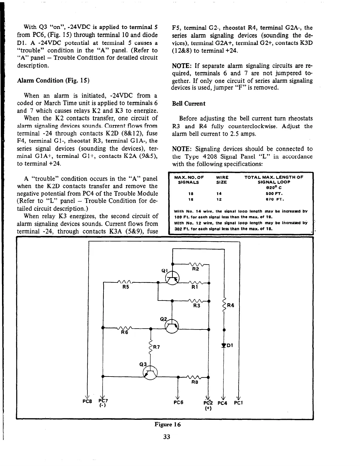
With 43 “on”,
-24VDC is applied to terminal 5
from PC6, (Fig. 15) through terminal 10 and diode
Dl. A -24VDC potential at terminal 5 causes a
“trouble” condition in the “A” panel. (Refer to
“A” panel - Trouble Condition for detailed circuit
description.
Alarm Condition (Fig. 15)
When an alarm is initiated, -24VDC from a
coded or March Time unit is applied to terminals 6
and 7 which causes relays K2 and K3 to energize.
When the K2 contacts transfer, one circuit of
alarm signaling devices sounds. Current flows from
terminal -24 through contacts K2D (8&12), fuse
F4, terminal Gl-, rheostat R3, terminal G 1 A-, the
series signal devices (sounding the devices), ter-
minal Gl A+, terminal G l+, contacts K2A (g&5),
to terminal +24.
A “trouble” condition occurs in the “A” panel
when the K2D contacts transfer and remove the
negative potential from PC4 of the Trouble Module
(Refer to “L” panel - Trouble Condition for de-
tailed circuit description.)
When relay K3 energizes, the second circuit of
alarm signaling devices sounds. Current flows from
terminal -24, through contacts K3A (5&g), fuse
F5, terminal G2-, rheostat R4, terminal G2A-, the
series alarm signaling devices (sounding the de-
vices), terminal G2A+, terminal G2+, contacts K3D
(12&8) to terminal +24.
NOTE: If separate alarm signaling circuits are re-
quired, terminals 6 and 7 are not jumpered to-
gether. If only one circuit of series alarm signaling
devices is used, jumper “F” is removed.
Bell Current
Before adjusting the bell current turn rheostats
R3 and R4 fully counterclockwise. Adjust the
alarm bell current to 2.5 amps.
NOTE: Signaling devices should be connected to
the Type 4208 Signal Panel “L” in accordance
with the following specifications:
MAX. NO.OF WIRE
SIGNALS SIZE
19 14
18
12
TOTAL MAX. LENGTH OF
SIGNAL LOOP
63200 c
500 FT.
a70 FT.
With No. 14 wire, the signal loop length may be increased by
109 Ft. for each signal less than the max. of tg.
With No. 12 wire, the iignal loop length may be iticrea’nd’bj
302 Ft. for each signal less than the max. of lg.
V
PC6
Figure 16
33