TYPE 4208 “M”
SUPERVISION RELAY MODULE
INTRODUCTION
The “M” module is used in a 4208 Fire Alarm
System when DC signal panels F, G, N, Z (C and V
obsolete) are used with an “AX” control panel.
Since a standby battery is not used with an
“AX” panel, the “M” module is used to supervise
the signal panels in case the signal panel power sup-
ply fails. Without an “M” panel the signal panel
power supply could fail and no indication would
show on the “AX” panel.
Only one “M” module is required per “AX”
panel regardless of the number of signal panels used
in the system.
The “M” module can be mounted in a panel of
its own or in any available space.
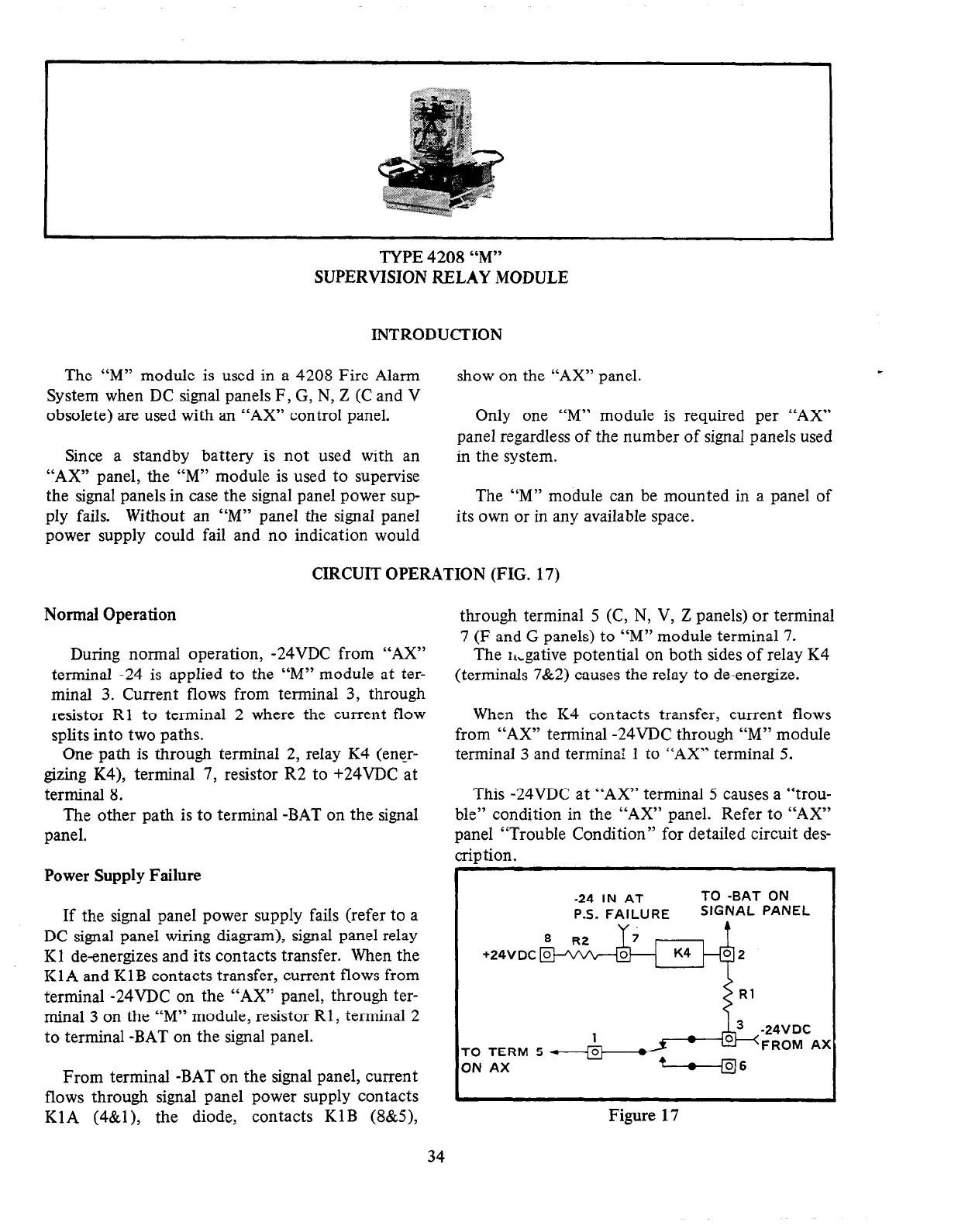
CIRCUIT OPERATION (FIG. 17)
Normal Operation
During normal operation, -24VDC from “AX”
terminal -24 is applied to the “M” module at ter-
minal 3. Current flows from terminal 3, through
resistor RI to terminal 2 where the current flow
splits into two paths.
One path is through terminal 2, relay K4 (ener-
gizing K4), terminal 7, resistor R2 to +24VDC at
terminal 8.
The other path is to terminal -BAT on the signal
panel.
Power Supply Failure
If the signal panel power supply fails (refer to a
DC signal panel wiring diagram), signal panel relay
Kl de-energizes and its contacts transfer. When the
Kl A and KlB contacts transfer, current flows from
terminal -24VDC on the “AX” panel, through ter-
minal 3 on the “M” module, resistor Rl, terminal 2
to terminal -BAT on the signal panel.
From terminal -BAT on the signal panel, current
flows through signal panel power supply contacts
KlA (4&l), the diode, contacts KlB (8&S),
through terminal 5 (C, N, V, Z panels) or terminal
7 (F and G panels) to “M” module terminal 7.
The r,,gative potential on both sides of relay K4
(terminals 7&2) causes the relay to de-energize.
When the K4 contacts transfer, current flows
from “AX” terminal -24VDC through “M” module
terminal 3 and terminal 1 to “AX” terminal 5.
This -24VDC at “AX” terminal 5 causes a “trou-
ble” condition in the “AX” panel. Refer to “AX”
panel “Trouble Condition” for detailed circuit des-
trip tion.
-24 IN AT
TO -BAT ON
P.S. FAILURE
SIGNAL PANEL
TO TERM s * &
ON AX
/---:::e,,
06
Figure 17
34
 Loading...


