3 S4603-0001-13 1/2016
General Operating Specifications
Voltage 18 to 32 VDC, system supplied
Normal Operating Current 110 mA (with LED backlighting on)
Battery Standby Current
65 mA (during battery backup, LED backlighting is turned off after 30 seconds without
switch activity)
Alarm Current 140 mA maximum (LED backlighting is on and tone-alert is sounding)
Operating Temperature Range 32° to 120° F (0° to 49° C)
Operating Humidity Range Up to 93% RH, non-condensing at 100° F (38° C)
Communications
4100ES/4100U Capacity,
Per RUI Output
Type
RUI (Remote Unit Interface) external annunciator communications line SLC (signaling
line circuit)
Capacity
Up to 31 remote annunciators/MINIPLEX transponders per channel including the
4603-9101 LCD Annunciator, the 4602-9101 Status Command Unit (SCU), and
4602-9102 Remote Command Unit (RCU); refer to data sheet S4100-0031 for
additional 4100ES information
Wiring Requirements
RUI Data
Standard Wiring Type Unshielded twisted pair (UTP), 18 AWG (0.82 mm
2
) for most applications, see below
Wiring Characteristics
0.58 µF (580 nF) maximum capacitance between conductors; 35 maximum total
line resistance
Wiring Applications
Requiring Shielded,
Twisted Pair (STP)
1. Wiring that leaves the building. Also requires Isolated Loop Circuit Protectors on
each end, refer to data sheet S2081-0007 for 2081-9027 (200 mA), or
S2081-0008 for 2081-9028 (5 A)
2. Wiring run in 500 ft (152 m) or more of conduit.
3. Wiring closely bundled with standard IDNet communications or TrueAlert
addressable communications (not required when run with IDNet+
communications).
Class B “T-Tap” wiring
distance
Up to 10,000 ft (3048 m) total wiring; up to 2500 ft (762 m) to farthest device
Class X wiring distance Up to 2500 ft (762 m)
Power Wiring 18 to 12 AWG (0.82 mm
2
to 3.31 mm
2
) wires for 24 VDC system power
Earth Wiring
A dedicated earth ground connection to the electrical box is required for proper ESD
and EMI protection; wire in accordance with NFPA 70 (National Electrical Code)
Article 250
Mounting Information
NOTE: General Conduit Entrance
Requirement
Conduit entrance must be located a minimum of 2 ¾” (70 mm) from the front of the
box to clear assembly
Trim Dimensions 4 ½” H x 11
13
⁄
16
” W (114 mm x 300 mm)
Standard Trim Finish Steel, painted beige
4603-9111, Optional Trim
Brushed stainless steel (ordered separately); supplied with both slotted and tamper
resistant screws
Boxes for Flush Mounting
(supplied by others)
6-Gang, 3 ½” (89 mm) deep: RACO 965, 6-gang masonry box; RACO 590, gangable
switch box, 6 required; or equal
2975-9206, Surface Mount Box Option (ordered separately)
Dimensions 11
31
⁄
32
” W x 4 ⅝” H x 2 ¾” D (304 mm x 117 mm x 70 mm)
Finish Painted steel, ivory finish
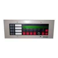
4603-9101 LCD Annunciator Specifications
For additional information, refer to Installation Instructions 579-979.
 Loading...