Do you have a question about the Simplex 4010ES Series and is the answer not in the manual?
The Simplex 4010ES and 4100 4120-Series Class A/Class B Zone Modules are designed for use in fire alarm and security systems, providing an interface for various initiating devices. These modules can be configured to support either Class A or Class B wiring, and can handle both fire initiating devices and security devices, depending on the specific model.
These modules serve as an essential component in a fire alarm control panel (FACP) or an expansion bay, allowing the system to monitor multiple zones for alarm or supervisory conditions. They are capable of connecting to a range of initiating devices, such as smoke detectors, heat detectors, manual pull stations, waterflow switches, and tamper switches. The primary function is to detect signals from these devices and transmit them to the FACP for processing and appropriate action.
The modules are available in several configurations:
The modules communicate with the FACP via a serial communication line. Each module is assigned a unique address within the FACP, which is configured using a bank of DIP switches (SW1-2 through SW1-8). An additional switch (SW1-1) sets the baud rate for communication and must be set to ON.
The modules can be installed in various back boxes and bays, including 2975-91xx Back Boxes (4100), 2975-94xx Back Boxes (4100U/4100ES), and 4010ES Back Boxes.
After any programming operation or change in site-specific software, a reacceptance test is required to ensure proper system operation in accordance with NFPA72.
The modules are designed for reliable operation with minimal ongoing maintenance beyond the required reacceptance testing after system changes. Their robust design and adherence to wiring guidelines contribute to long-term stability in fire alarm and security applications.
| Communication Ports | RS-232, USB |
|---|---|
| Notification Appliance Circuits (NACs) | 4 NACs |
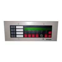
| Display | LCD display |
| Annunciation | LED annunciators |
| Agency Listings | UL, FM, CSFM |
| Max Zones | 99 |
| Battery Backup | 24-hour standby |
| Operating Temperature | 0°C to 49°C (32°F to 120°F) |
| Humidity Range | 10% to 93% non-condensing |
| Dimensions | 368 mm x 318 mm |