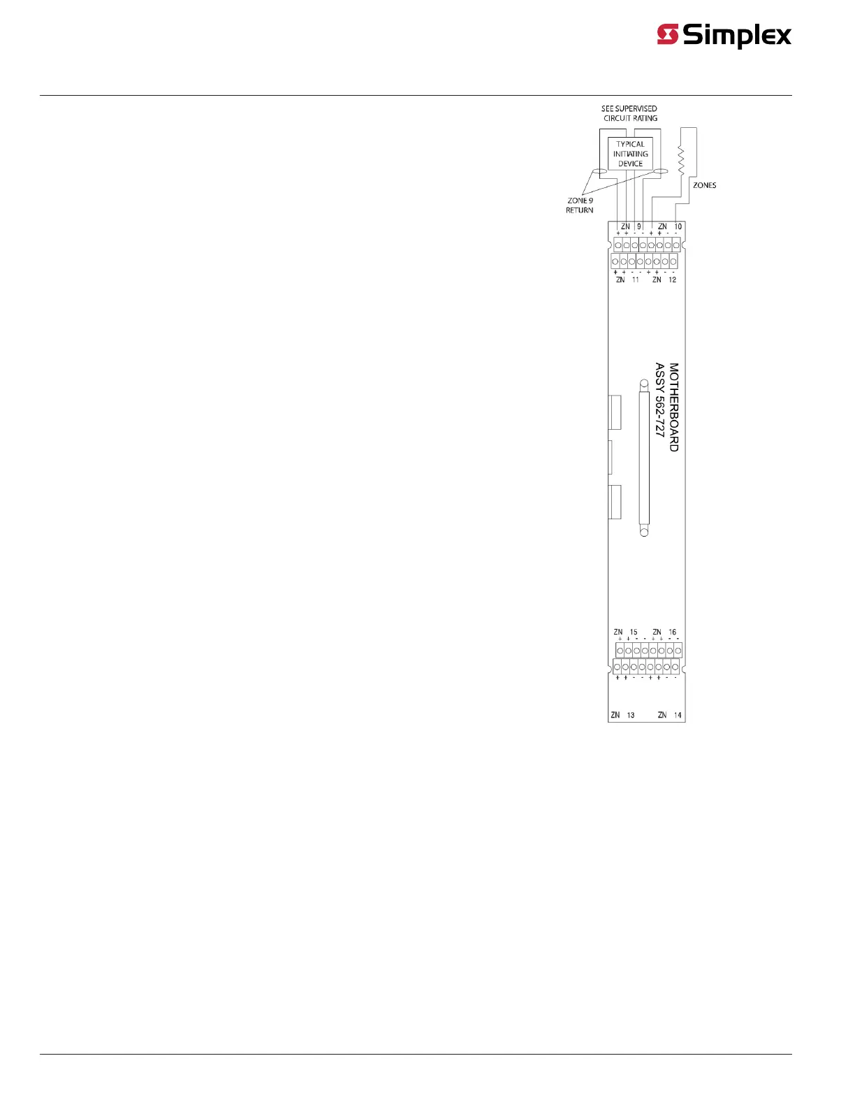
Specific Wiring Guidelines for Class A Zone Modules
• If a zone is not used, connect a 3.3 K, 1 W resistor (378-017) across zone
terminals as shown in the figure.
• All device wiring must be terminated to the appropriate zone as shown on Zone
1.
• Wiring shown in the figure is typical. All detector types may be wired to any zone.
• Each zone is marked with its circuit number. Refer to the 4100 Programmer Report,
which references the exact wires connected.
• For zones that connect contacts only, the maximum line resistance is 800 Ohms.
Figure 18: Class A Monitor Zone Wiring
Class A Monitor Zone – Waterflow Switch Wiring
Waterflow Switch Wiring
Figure 19 shows a waterflow switch wired to a Class A monitor zone. Adhere to both the general wiring guidelines outlined earlier in this document and
the specific wiring guidelines shown below.
page 19 579-205 Rev. H
4010ES and 4100 4120-Series Class A/Class B Zone Modules Installation Instructions