Use the following procedure when installing motherboards in an expansion bay. Start with the second slot from the left and fill to the right.
1. Orient the motherboard with the connector labeled J1 on the right and the header labeled P1 on the left.
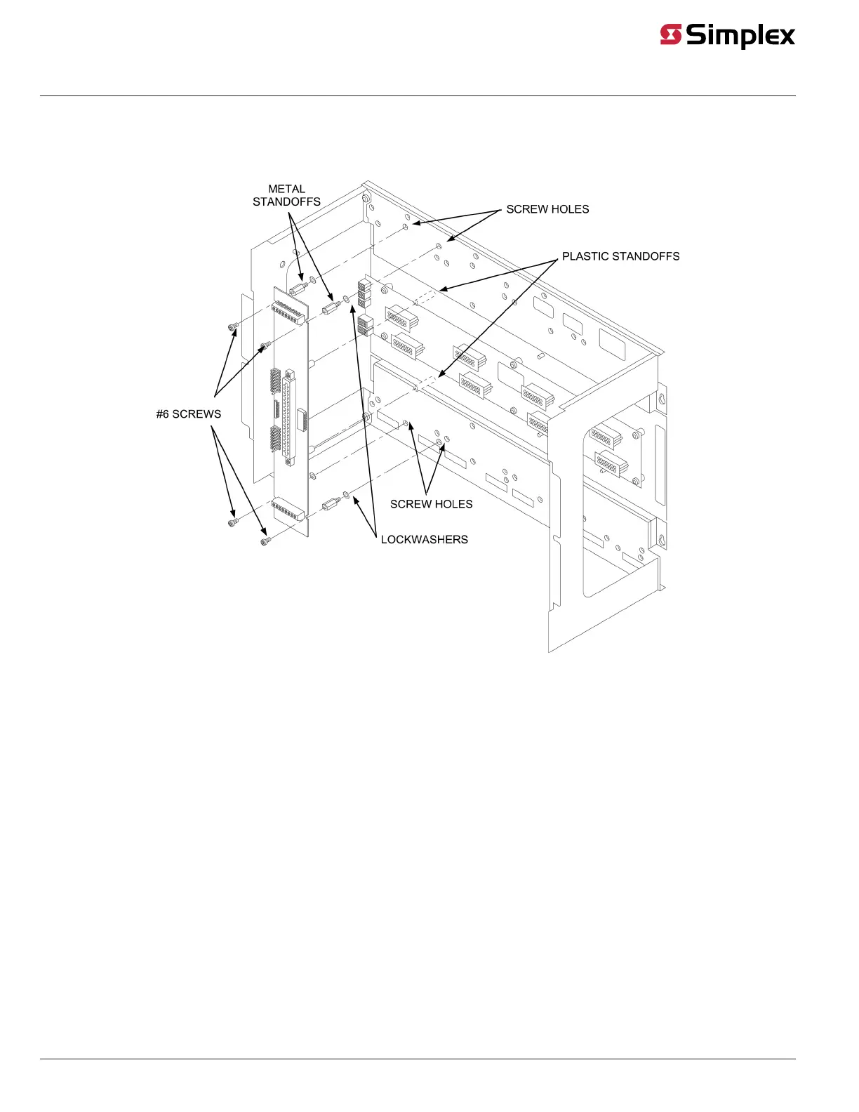
2. Attach four metal threaded standoffs and lockwashers into the screw holes on the chassis.
3. Attach two grey plastic standoffs to the motherboard socket mounting screws.
4. Secure the motherboard to the standoffs using four #6 torx screws as shown in Figure 9.
Figure 9: Installing the Motherboard in a 4100U/4100ES Expansion Bay
5. If you are installing the leftmost motherboard, connect a 733-525 Power and Communication Harness. Continue to the next topic to connect the
harness.
Connecting the 733-525 Harness
If you need to connect a 733-525 Harness to a motherboard, refer to Figure 10 and follow these steps. Make sure to route the power and
communication wiring on the left side of the bay.
1. Connect one end of the harness to a motherboard in an adjacent bay. If the adjacent bay is the CPU bay with no additional motherboards,
connect the harness to the P8 and P7 connectors of the CPU motherboard.
a. Insert the harness connector with the blue wire into the P8 connector. Note that the P8 connector has eight pins. Insert the harness
connector on either the top four pins or the bottom four pins, not in the middle.
b. Insert the harness connector with the white wire into the P7 connector. Note that the P7 connector has eight pins. Insert the harness
connector on either the top four pins or the bottom four pins, not in the middle.
If the adjacent bay is an expansion bay or a CPU bay with additional motherboards, connect the harness to the P2 and P3 connectors of the
motherboard installed in the leftmost slot. (If a 4100-0155/4120-0155 SDACT, 4100-6052 Event Reporting DACT, 4100-6053 Point Reporting
DACT, or a 4100-0153/4120-0153 CCDACT occupies the leftmost slot, connect the harness to the motherboard in the second slot from the
left.) Connect the harness as follows:
a. Insert the harness connector with the blue wire into the P2 connector. Note that the P2 connector has eight pins. Insert the harness
connector on either the top four pins or the bottom four pins, not in the middle.
b. Insert the harness connector with the white wire into the P3 connector. Note that the P3 connector has eight pins. Insert the harness
connector on either the top four pins or the bottom four pins, not in the middle.
2. Connect the other end of the harness to the leftmost motherboard in the next bay, as described below. Make sure to route the wiring on the
left side of the bay.
a. Insert the harness connector with the blue wire into the P2 connector. Note that the P2 connector has eight pins. Insert the harness
connector on either the top four pins or the bottom four pins, not in the middle.
page 9 579-205 Rev. H
4010ES and 4100 4120-Series Class A/Class B Zone Modules Installation Instructions