EasyManua.ls Logo

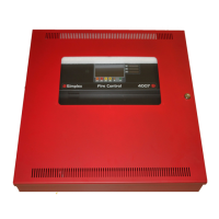
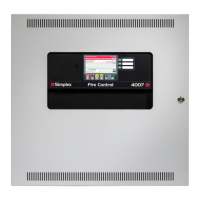
Simplex 4007ES Hybrid User Manual

Simplex 4007ES Hybrid
44 pages
To Next Page IconTo Next Page
Page #1 background imageLoading...
Page #1 background image
4007ES and 4007ES Hybrid
Fire Alarm Systems
Installation
Manual
579-1102
Rev. E

Table of Contents

Other manuals for Simplex 4007ES Hybrid

Questions and Answers:

Simplex 4007ES Hybrid Specifications

General IconGeneral
Event History Log1000 events
Operating Voltage24 VDC
Network CapabilityYes
Power Supply120/240 VAC, 50/60 Hz
Battery BackupYes
ExpandableYes
User InterfaceLCD display and keypad
Remote MonitoringYes
NAC Output2.5 A per circuit
Annunciator SupportYes
Operating Temperature32°F to 120°F (0°C to 49°C)
Humidity RangeUp to 93% RH, non-condensing

Summary

Copyrights, Trademarks, Cautions, Warnings, and Regulatory Info

Cautions and Warnings

Safety instructions and hazard alerts for installation and operation.

Chapter 2 Installation

Mounting the 4007ES Panels

Instructions for physically securing the panel to walls.

Wiring

Chapter 3 NAC Power Supply

NAC Power Supply Specifications

Technical details and current draw of the NAC power supply.

NAC Section Troubleshooting

Guidance for diagnosing and resolving issues with the NAC power supply.

NAC Section

NAC Section Wiring

Procedures for wiring the NAC section.

NAC Class A Wiring

NAC Class B Wiring

NAC Troubleshooting

Chapter 4 IDNAC Power Supply

IDNAC Power Supply Specifications

Technical details and current draw of the IDNAC power supply.

IDNAC Troubleshooting

Guidance for diagnosing and resolving issues with the IDNAC power supply.

IDNAC Section

IDNAC Section Wiring

Procedures for wiring the IDNAC section.

IDNAC Class B Wiring

Troubleshooting

IDNAC Channel Troubleshooting

Guidance for diagnosing and resolving issues with IDNAC channels.

Chapter 5 4007ES Power Supplies

Power Supplies Specifications

Technical specifications for the power supplies.

Wiring Guidelines

Best practices and regulations for system wiring.

IDNet Wiring

Procedures for wiring the IDNet section.

IDNet Troubleshooting

Guidance for diagnosing and resolving issues with the IDNet section.

IDNet Class A Wiring

IDNet Class B Wiring

Power Supply Troubleshooting

Chapter 6 Optional Modules and Cards

Appendix A ULC Programming Requirements

Common Earth Fault Ground and Common Trouble Indicator

Procedure for configuring indicators for faults.

ULC Programming Requirements: Common Fault Indicator

Related product manuals