••• 4 •••
DANGER: Only use hydraulic cylinders in a coupled system. Never use a cylinder with unconnected couplers. If the
cylinder becomes severely overloaded, components can fail catastrophically causing severe personal injury or death.
3.0 TECHNICAL SPECIFICATIONS
G5 Air Series
Operating Pressure 10,000 PSI (700kg/cm
2
)
Motor Rating Rotary Air Valve, 3 hp Motor (13,000 rpm)
90 psi / 50 cfm
Flow Rate 700 cu. in./ min. @ 1,100 psi, 55 cu. in / min. @ 10,000 psi
Maximum Operating Temperature 170F - (65C)
4.0 WORKING PRESSURE
The pump’s maximum working pressure is 10,000 PSI (700kg/cm
2
). Make sure that all hydraulic equipment such as
rams, hoses, etc. used with this pump are rated at 10,000 PSI (700kg/cm
2
) operating pressure.
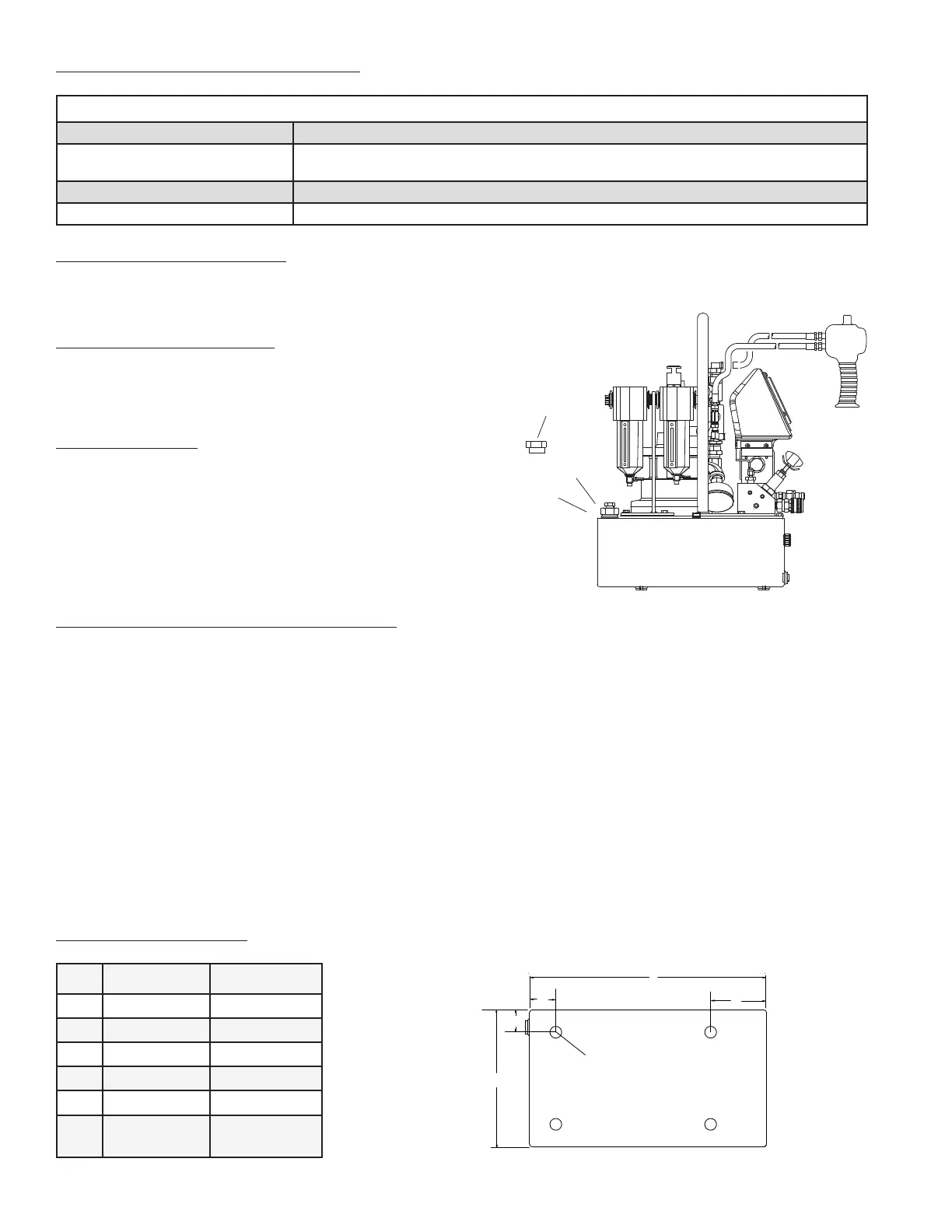
4.1 INSTALL VENT PLUG
Remove SHIPPING PLUG (A) and install VENT PLUG (B) into cover plate.
4.2 ADDING OIL
Remove OIL FILLER CAP (C) and add SIMPLEX Hydraulic Oil into reser-
voir. Oil level should not exceed 1” from the reservoir cover.
As a “rule of thumb” oil should be visual in site window when the unit is
powered down and all connected tools or cylinders are retracted.
4.3 INSTALL HYDRAULIC CONNECTIONS
Use only cylinders, tools, hoses and accessories rated at 10,000 PSI
(700kg/cm
2
). Remove the shipping plugs from the ports to connect your coupling(s) or hose(s) to manifold. Use 1.5
wraps of Teon tape (or suitable thread sealant) on all threads, leaving the rst complete thread free of tape to ensure
no foreign matter enters the hydraulic circuit.
When making connections with quick dis-
connect couplings, make sure the couplings
are fully engaged. Threaded connections
such as ttings, gauges, etc. must be se-
curely tightened and leak free.
WARNING: Loose or improperly threaded
ttings can be potentially dangerous if
pressurized; however, severe over tighten-
ing can cause premature thread failure.
Fittings need to be tightened secure & leak
free. Never hold or stand directly in line with
any hydraulic connections while pressur-
izing. Never grab, touch or in any way come
in contact with a hydraulic pressure leak.
Escaping oil can penetrate the skin and a
serious injury can result.
CAUTION: Do not subject the hose to
potential hazards such as sharp surfaces, extreme heat or heavy impact.
Do not allow the hose to kink or twist. Inspect each hose for wear before it is used.
A
C
B
VENT PLUG OIL FILL LOCATION IS
APPLICABLE TO THE 1.5, 2.5, 5 &
10 GALLON RESERVOIRS
3 Way Solenoid Valve
4 Way Solenoid Valve
2 Way Manual
3 Way Manual
4 Way Manual
“A”
Port
“T”
Port
“T”
Port
“A”
Port
“B”
Port
“A”
Port
“T”
Port
“A”
Port
“B”
Port
“A”
Port