EasyManua.ls Logo

Simplicity SOVEREIGN 3415S - Page 19

Simplicity SOVEREIGN 3415S
40 pages
Print Icon
To Next Page IconTo Next Page
To Previous Page IconTo Previous Page
Loading...
I
I
i
i
i
i
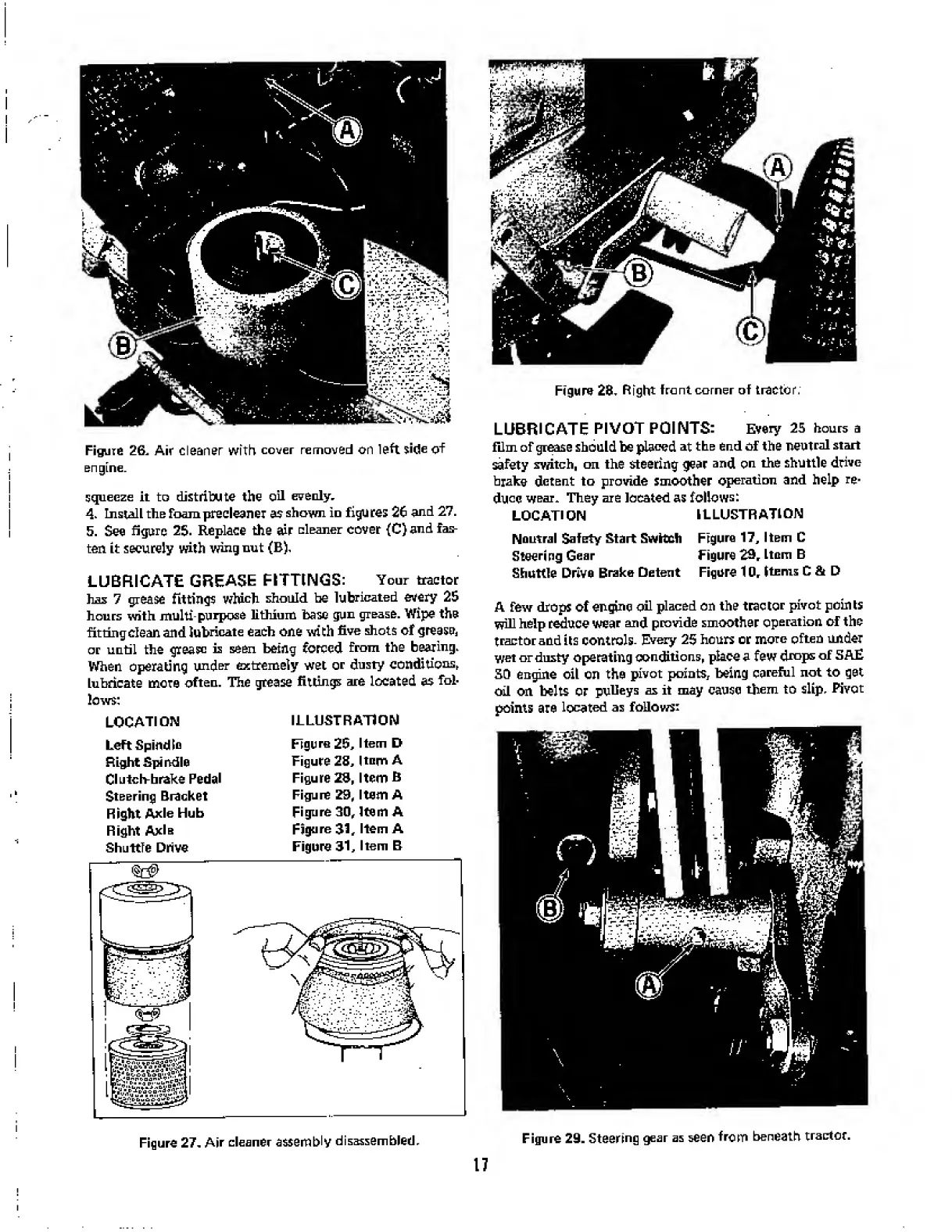
Figure
26.
Air
cleaner
with
cover
removed
on
left
side
of
engine.
squeeze
it
to
distribute
the
oil
evenly,
4.
Install
the
foam
precleaner
as
shown
in
figures
26
and
27.
5.
See
figure
25.
Replace
the
air
Gleaner
cover
(C)
and
fas¬
ten
it
securely
with
wing
nut
(B),
LUBRICATE
GREASE
FITTINGS:
Your
tractor
has
7
grease
fittings
which
should
be
lubricated
every
25
hours
with
multi-purpose
lithium
base
gun
grease.
Wipe
the
fitting
clean
and
lubricate
each
one
with
five
shots
of
greesu
d
or
until
the
grease
is
seen
being
forced
from
the
bearing.
When
operating
under
extremely
wet
or
dusty
conditions,
Lubricate
more
often.
The
grease
fittings
are
located
as
fol¬
lows:
LOCATION
Left
Spindle
Right
Spindle
Clutch-brake
Pedal
Steering
Bracket
Right
Axle
Hub
Right
Axla
Shuttle
Drive
ILLUSTRATION
Figure
25,
Item
D
Figure
28,
Item
A
Figure
28,
Item
B
Figure
29,
Item
A
Figure
30,
Item
A
Figure
31,
Item
A
Figure
31,
Item
B
Figure
28,
Right
front
corner
of
tractor;
LUBRICATE
PIVOT
POINTS:
Every
25
hours
a
film
of
grease
should
be
placed
at
the
end
of
the
neutral
start
safety
switch,
on
the
steering
gear
and
on
the
shuttle
drive
brake
detent
to
provide
smoother
operation
and
help
re¬
duce
wear.
They
are
located
as
follows:
LOCATION
ILLUSTRATION
Neutral
Safety
Start
Switch
Figure
17,
Item
C
Steering
Gear
Figure
29,
Item
B
Shuttle
Drive
Brake
Detent
Figure
10,
Items
C
&
D
A
few
drops
of
engine
oil
placed
on
the
tractor
pivot
points
will
help
reduce
wear
and
provide
smoother
operation
of
the
tractor
and
its
controls.
Every
25
hours
or
more
often
under
wet
or
dusty
operating
conditions,
place
a
few
drops
of
5AE
SO
engine
oil
on
the
pivot
points,
being
careful
not
to
get
oil
on
belts
or
pulleys
as
it
may
cause
them
to
slip.
Pivot
points
are
located
as
follows:
Figure
29.
Steering
gear
as
seen
from
beneath
tractor.
Figure
27.
Air
cleaner
assembly
disassembled.
17