11
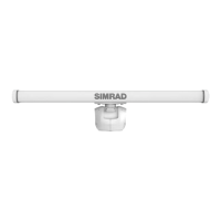
HALO 5000 pedestal
⚠
WARNING: Leave the waveguide protection cap on the pedestal while you mount it to your vessel. You should
only remove the cap just before you t the antenna to the pedestal.
Bolts and washers
The eight hex head bolts supplied are suitable for surfaces up to 25 mm (1”) in thickness.
• Use the 4 x M12 x 35 mm for a surface thickness from 5 mm (0.2”) up to 13 mm (1/2”).
• Use the 4 x M12 x 50 mm for a surface thickness from 13 mm (1/2”) up to 25 mm (1”).
If using longer bolts, ensure they are marine-grade stainless steel and allow for a minimum of 12 mm (0.3”) and maximum
of 20 mm (0.7”) of thread engagement in base of pedestal.
Use a at washer and a spring washer for each bolt.
If you are installing the pedestal onto a steel surface, also use the supplied plastic isolating washers.
1 Plastic isolating washer, M12 x 38
2 Flat washer, M12 x 36 x 3, 316 s/s
3 Spring washer, M12, 316 s/s
4 Bolt, hex head, M12, 316 s/s
Mounting
1 Place the mounting template in your desired installation location, observing the correct orientation.
¼ Note: Minor deviations in orientation should be corrected with the bearing alignment setting.
2 Check the location has enough room for the antenna to rotate.
3 Tape the template securely in place.
4 Drill pilot holes, then use a 13 mm (1/2”) drill bit to drill the four holes where shown on the mounting template.

 Loading...