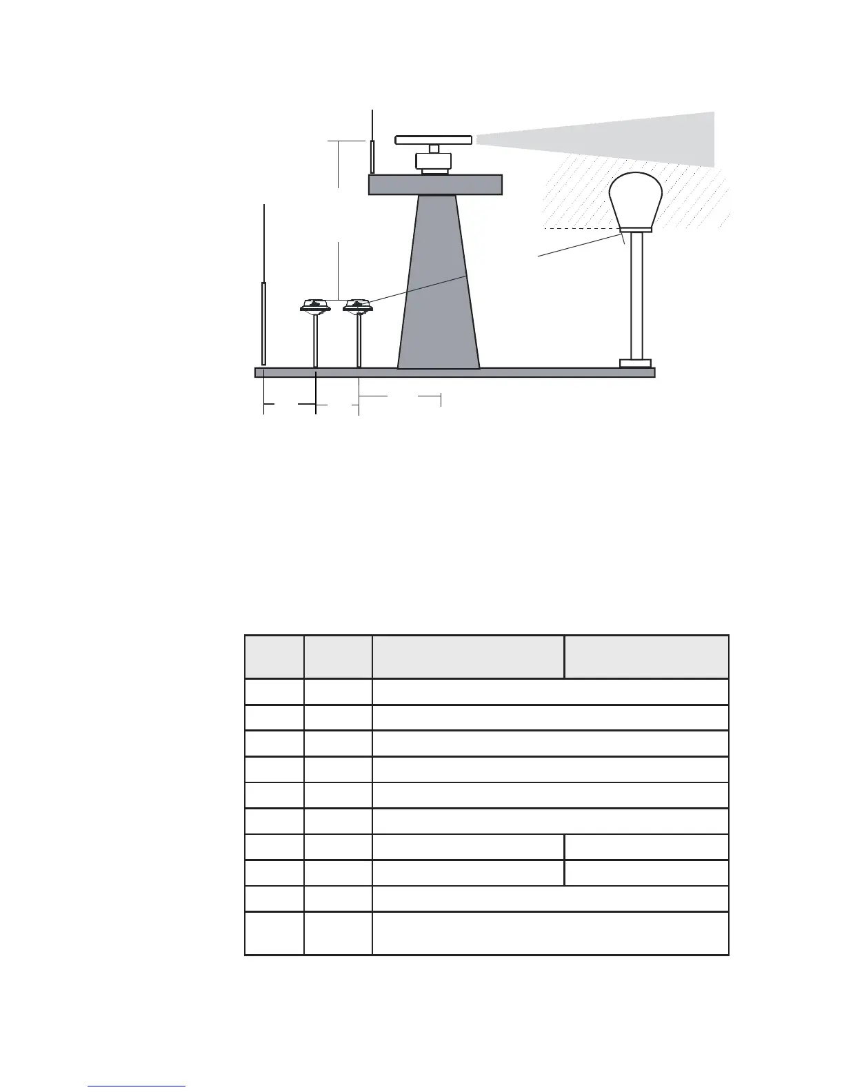
12 | Installation
MX521 Connector
The 10-pin male connector located at the underside
of the antenna unit provides the means to connect to
external power and the data interface. Please refer to the
chart below for the pin numbers, wire colors codes and
signal assignments.
Pin # Wire
Color
MX521 DGPS
Antenna
MX521 GPS
Antenna
1 BLK Negative Ground
2 RED +9 - 32 VDC
3 BLU MX Proprietary Message (MPM In (-)
4 BRN MX Proprietary Message (MPM In (+)
5 ORG GP S Out (-)
6 GRN GP S O ut (+)
7 YEL Beacon Status Out (-) Not used
8 WHT Beacon Status Out (+) Not used
9 PRPL RT C M IN (+)
10 PRPL/
GRY
RTCM IN (-)
•