EasyManua.ls Logo

Simrad MX521 - MX521 Connector Configuration

Simrad MX521
40 pages
Print Icon
To Next Page IconTo Next Page
To Previous Page IconTo Previous Page
Loading...
Installation | 17
MX521 Connector Conguration
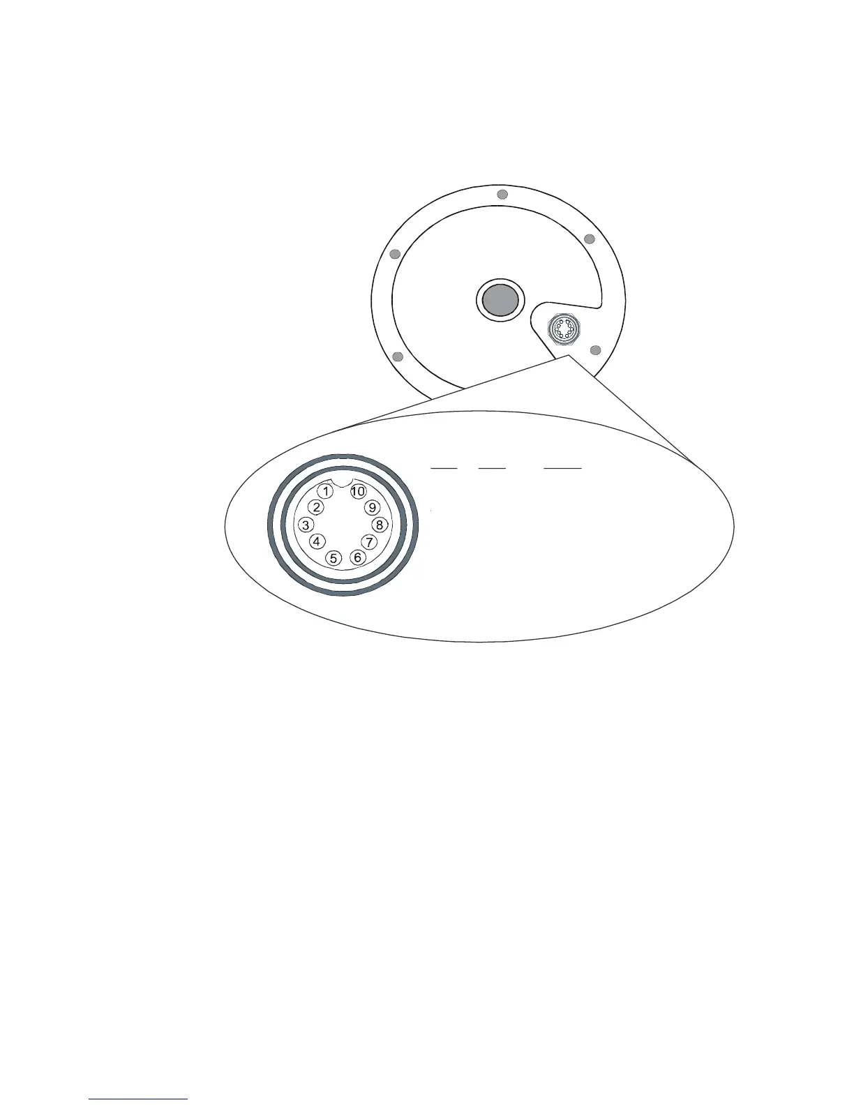
Refer to the diagram below for the POWER-DATA
connector located at the underside of the MX521A:
MX521 POWER-DATA Connector
Where:
Pins 1 & 2: Negative GND and +12 VDC power input.
Pins 3 & 4: MX proprietary message (MPM)
input port.
Pins 5 & 6: GPS output to the MX420 or other NMEA
0183 compatible devices.
Pins 7 & 8: Beacon monitoring signal output. Sends
the SNR, Signal and Frequency to the CDU.
Connects to Cable B of the MX420/8 CDU.
Pins 9 & 10: External RTCM Correction (Input).
1
6
9
1 0
2
3
8
4
7
5
Pin# Wire Signal
10
P
rpl/
G
ry
9
Purple
8
White
Beacon Status Out +*
7
Yellow
Beacon Status Out -*-
6
Green
GPS Out +
5
Orange
GPS Out -
4
Brown
MPM IN+
3
Blue
MPM
IN
-
2
Red
+
9
~32 VDC
1
Black
Negative GN
D
.
Ext. RTCM IN-
Ext. RTCM IN+
*
Not available with MX521G models

Related product manuals