Issue 4.0 24/09/03 SIMRAD
8
3 ASSEMBLY INSTRUCTIONS
General Assembly : TP10
Motor and Drive Assembly. The Bottom Case Assembly is supplied fitted with appropriate
cables. Refer to detail in Drawing Number E03504 and insert the Push Rod Seal E00747, which
has a taper inner bore, into the case with the larger bore of the seal facing outwards. Fit “O” Ring
190026, spacer E02870 and End Cap E02495 and push home. Fit Retainer E03084 and secure
with 2 screws 200002 to hold the end cap, ensuring it is pushed fully in when the two screws are
tightened. Using a small brush, grease the ‘trough’ area and the bore which houses the seal, “O”
ring and spacer. Insert the Drive Assembly E03264 ensuring that the bearing slots into the bearing
housing and the drive belt 280027 is fitted around the pulley. Insert the Motor Assembly E02788
fitted with front and rear Motor Mounts E02502 and E02503 ensuring that the blue wire is
uppermost, the motor sits snugly into the bottom of the retaining slot and the drive belt is engaged
over the motor drive pulley. Check that the motor, belt and drive screw assembly move freely. Fit
Bearing Clamp E02497 on two Nylon Spacers 200115, one on each screw 200137, into the case
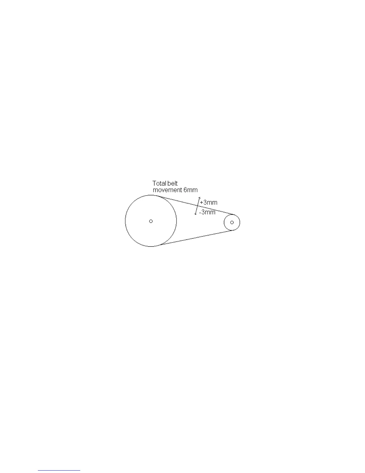
bottom and secure the bearing with the two screws. Refer to the sketch below and check that the
belt tension is within +/- 3mm.
Fit the Tiller Connector E02607 into the end of the Push Rod E02522 and screw in, finger tight.
Hall Effect PCB. Fit the Hall effect PCB onto the 2 pillars using 2 nylon washers 200037 as
spacers between the pillars and the PCB, and 2 screws 200139. Ensure that the separation
distance between the Magnets (E03208), seated in the 71 Tooth Pulley (E02505), and the Hall
Effect Devices (140010) does not exceed 1mm.
Main PCB. Feed the power, motor and feedback leads through the 2 grommets 190036 and the
appropriate grommet in the PCB Assembly cover and solder the connections to the PCB. Refer to
drawing and push PCB Assembly firmly onto the four bosses in the PCB Cover E02680. Clip the
compass Assembly E02637 into the Drilled PCB Cover E02680, it can only be fitted one way
round, ensuring that the lugs on the compass assembly line up with the 2 holes in the PCB cover
and push in. Refer to drawing E03504 and ensuring that the wires from the compass to the
connector lay over the PCB, insert plug into the socket on the PCB. Ensure all wires are clear of,
and not fouling the PCB cover seal, and position the PCB Cover complete with the PCB and
compass into the Case Top Assembly E02612. Screw down the PCB cover with 6 screws 200139
and fully tighten. Position the two grommets into case top, and push home into the two slots.
Wrap the ‘Wits” fixing 200196 around the cable loom, and using a screw 200139 fix into the top
cover.