1616
SUREFIRE ELECTRONIC IGNITION SYSTEM
S.I.T. PROFLAME 1 TROUBLESHOOTING
SimTech Proflame I
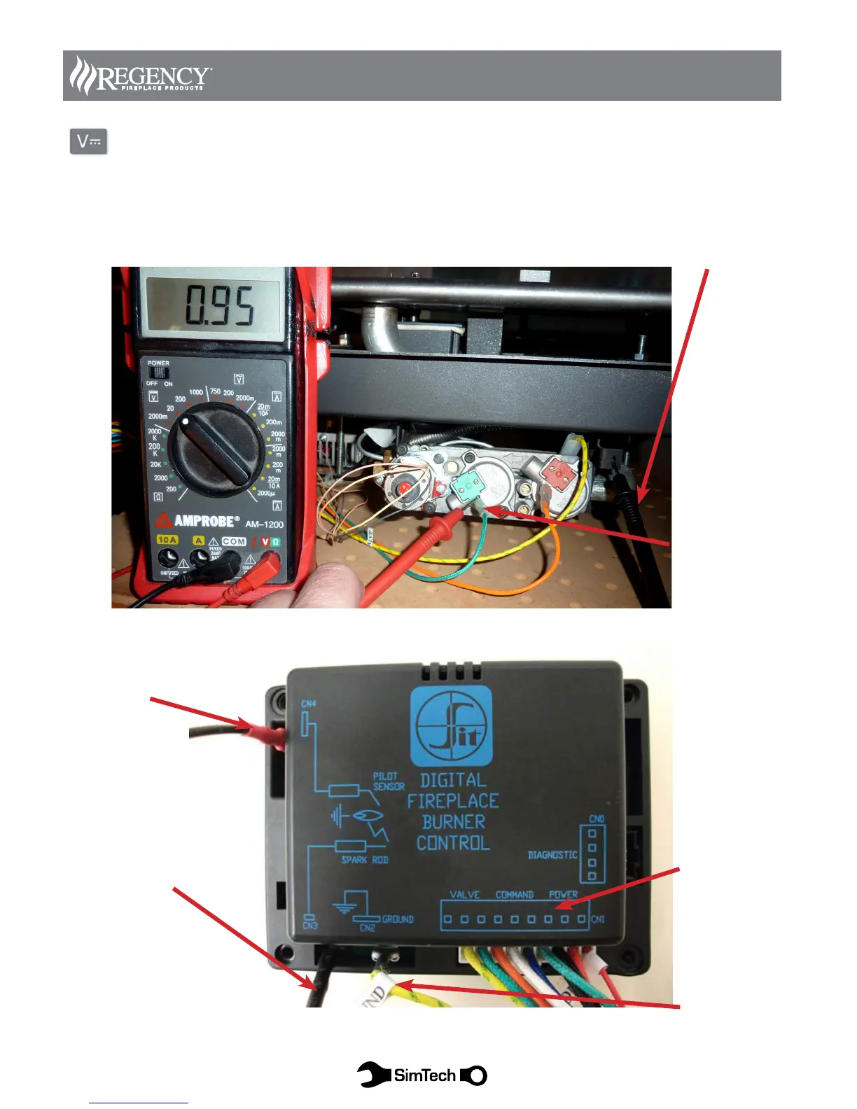
Diagram 15 DC VOLTS TEST (VDC)
With system complete conduct the following test:
Check voltage at EV2 main burner coil with the green wire connected to the valve. With the leads in place
switch the unit on. For approximately 2 seconds the voltage should read 4-6 vdc then drops to .5-1 vdc. If there
is voltage replace the valve. If there is not voltage replace the DFC.
Diagram 16
9 8 7 6 5 4 3 2 1
CN1 Nine Pin
Molex connector
locations num-
bered right to left
Second lead goes
to valve body
(or Ground)
EV2 (Green
Tab) This wire
must stay con-
nected for this
test.
CN4 Flame Sensor
(Red Sleeve)
CN3 Spark Electrode
(Black Sleeve)
CN 2 Ground