58
MAXITROL GV60 IGNITION SYSTEM
TROUBLESHOOTING
Maxitrol GV60
Diagram 1b
Diagram 1c
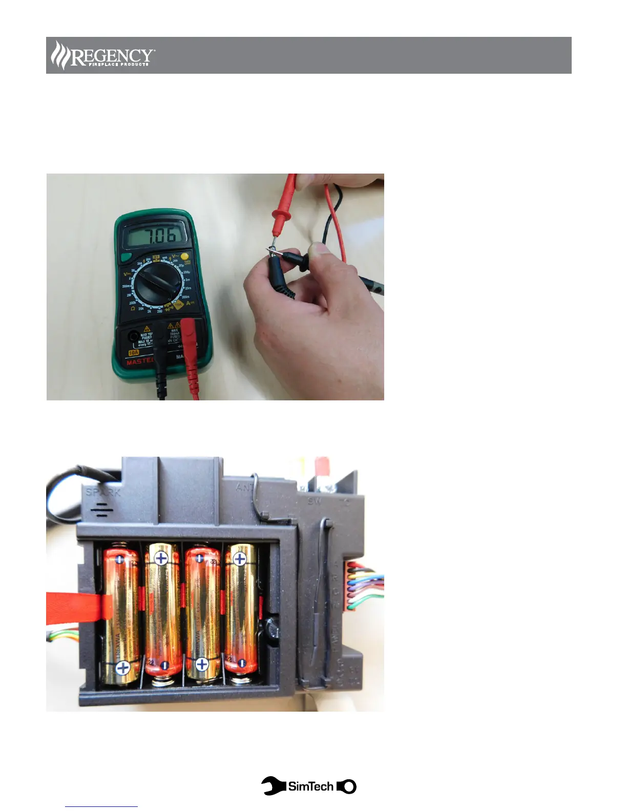
Diagram 1b:
Verify AC Adaptor output.
Set meter to Volts DC in the lowest range above 10 VDC.
With the AC adaptor plugged in, place the (+) Positive probe inside plug tip, and.
Place the (-) Negative probe on exterior of plug tip.
Meter should read approximately 6 -7 VDC.
If NO voltage out of AC adaptor Verify presence of 110 VAC from outlet, otherwise replace AC adaptor.
Diagram 1c:
Verify batteries are fully seated and with the correct polarity.