57
MAXITROL GV60 IGNITION SYSTEM
TROUBLESHOOTING
Maxitrol GV60
Diagram 1
Diagram 1a
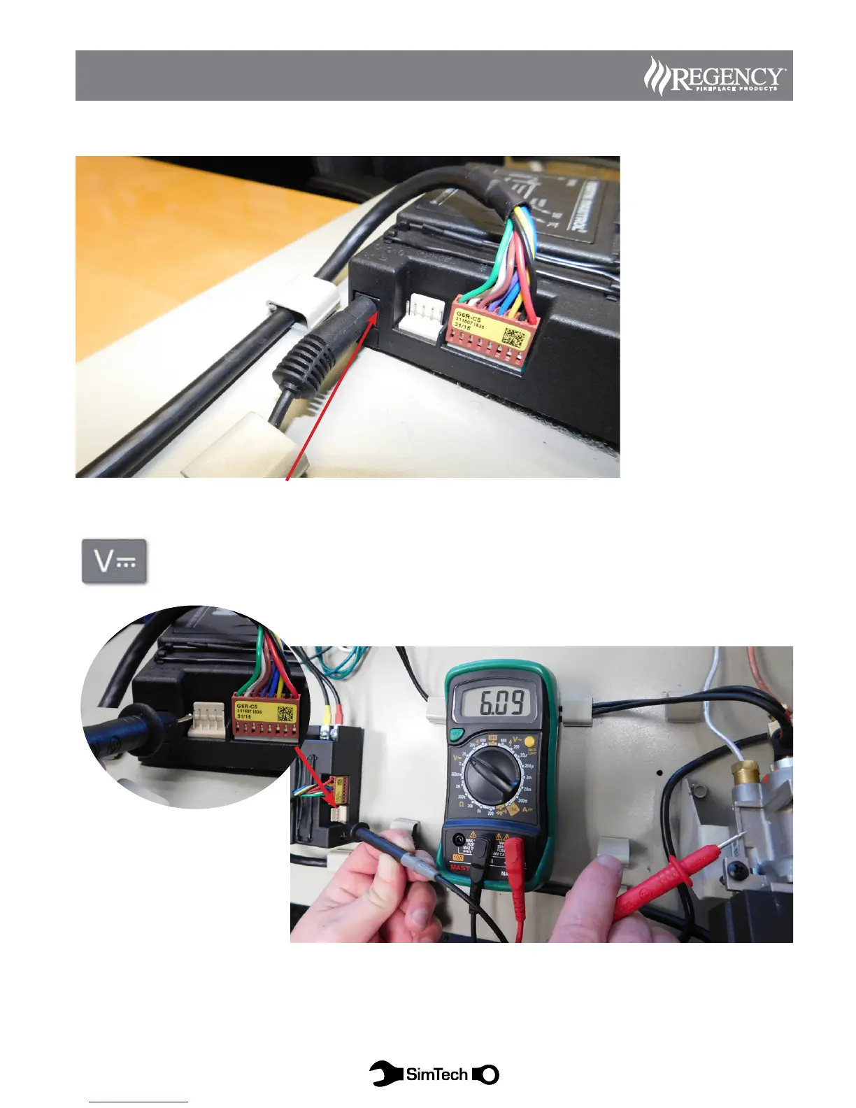
Diagram 1: Ensure AC adaptor is connected to Receiver.
Volts DC (vdc) Set meter to voltage DC, in the lowest possible range above 10VDC.
Place (+) positive probe on the left most pin of the 5 pin connector at the Receiver.
Place (-) negative probe to ground (valve body, ground lug or bare metal of chassis).
The meter should read between 5-6 VDC. If lower, change batteries or install AC adaptor and test.
Verify AC adaptor is connected to receiver. If not, connect and
test again.