TLU 600/610
Page 2/20
NOSP 14540-04 (JULY 2011)
CONTENTS
1.
INTRODUCTION ............................................................................................................. 3
1.1.
1.1.
I
DENTIFICATION AND MARKING
.................................................................................... 3
1.2.
1.2.
F
UNCTIONS
............................................................................................................. 4
1.3.
1.3.
R
EMOTE CONTROLLER CONSTRUCTION
......................................................................... 5
2.
CERTIFICATION ............................................................................................................. 7
3.
OPERATION ................................................................................................................... 8
1.4.
3.1.
S
WITCHING ON
........................................................................................................ 8
1.5.
3.2.
PASS WORD
............................................................................................................. 8
1.6.
3.3.
MENU
.................................................................................................................... 9
1.7.
3.4.
PICTOGRAMS
......................................................................................................... 11
4.
TECHNICAL SPECIFICATIONS ..................................................................................... 15
5.
MAINTENANCE ............................................................................................................ 15
1.8.
5.1.
C
LEANING
............................................................................................................ 15
1.9.
5.2.
C
HANGING A BATTERY UNIT
...................................................................................... 15
6.
PACKAGING AND TRANSPORT .................................................................................... 15
7.
STORAGE ..................................................................................................................... 15
8.
Contact details ............................................................................................................. 19
INDEX OF FIGURES
Figure 1: TLU Label ............................................................................................................. 3
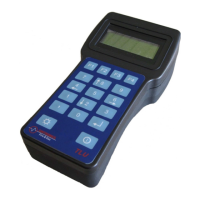
Figure 2: the remote controller............................................................................................ 5
Figure 3: the remote controller key pad ............................................................................... 6
Figure 4: connection established screen ........................................................................... 10
Figure 5: connection to multiple sensors screen ............................................................... 10
Figure 6: battery charging indicator ................................................................................... 11
Figure 7: low battery level indicator ................................................................................... 11
Figure 8: connection indicator ........................................................................................... 12
Figure 9: good communication indicator ............................................................................ 12
Figure 10: poor communication indicator .......................................................................... 13
Figure 11: charging connection .......................................................................................... 13
APPENDICES
APPENDIX 1 : EC conformity declaration for TLU600 ......................................................... 16