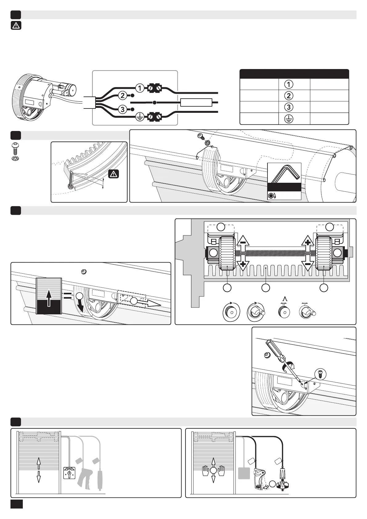
Connection diagram (all Centris range)
5
Attaching the shutter (all Centris range)
6
End limits adjustment (all Centris range)
7
Use
8
230V - 50Hz
(120V - 60Hz)
UNSTABLE SWITCH
PE
L
N
16A FUSE
230V - 50Hz120V - 60Hz
Green / yellow
Green
PE
Blue
White
N
Brown
Black
L1
Black
Red
L2
7.1 - Identiying the end limits
- The main power line must have a safety protection in accordance with the rules of the country of use.
- The power supply circuit must be equipped with an omnipolar cutting device with an openning gap of 3 mm minimum. (EN60335-1 standard).
- Switch off the installation during connection. After connection: switch your installation on, check the direction of the operator rotation.
If the direction is not the desired one, disconnect power and invert the brown and black wires (230V power) or the red and black wires
(120V power).
- A "dead man" type control can be done only by use of an unstable switch.
a - Sliding end limits box cover
b & c - Removable memory rings.
d & e - Rotary adjusting wheels.
f & g - Electric switches.
h - Motor crown.
i - Guiding blades.
7.2 - Adjustment
- Down end limit:
1 - Put electrically the shutter to the DOWN wished position.
2 - Remove the memory ring of the right side (c).
3 - Turn the right adjusting ring (e) in the “-” direction until to activate the switch (g).
- Up end limit:
1 - Put electrically the shutter to the UP wished position. (noise of the blades i)
2 - Move the shutter down up to the oor.
3 - Remove the memory ring of the left side (b).
4 - Turn the left adjusting ring (d) 2 turns in the “-” direction (tip: mark the wheel with a pencil).
- Move the shutter up and down to check the end limits positions. If necessary, turn the adjusting
wheels in the “+” direction to increase shutter travel or in the “-” direction to decrease shutter travel.
7.3
CBL Z 3x12 screw
4/4
- Electrically with key switch.
- Manually thanks to the
declutching system.
 Loading...