User Manual of A90 Series Inverter
118
Operation
Parking
Forward/
reverse
RUN
Xi
F/R
COM
24V
Inverter
RUN
F/R
f
-f
Output
frequency
Time
Xi
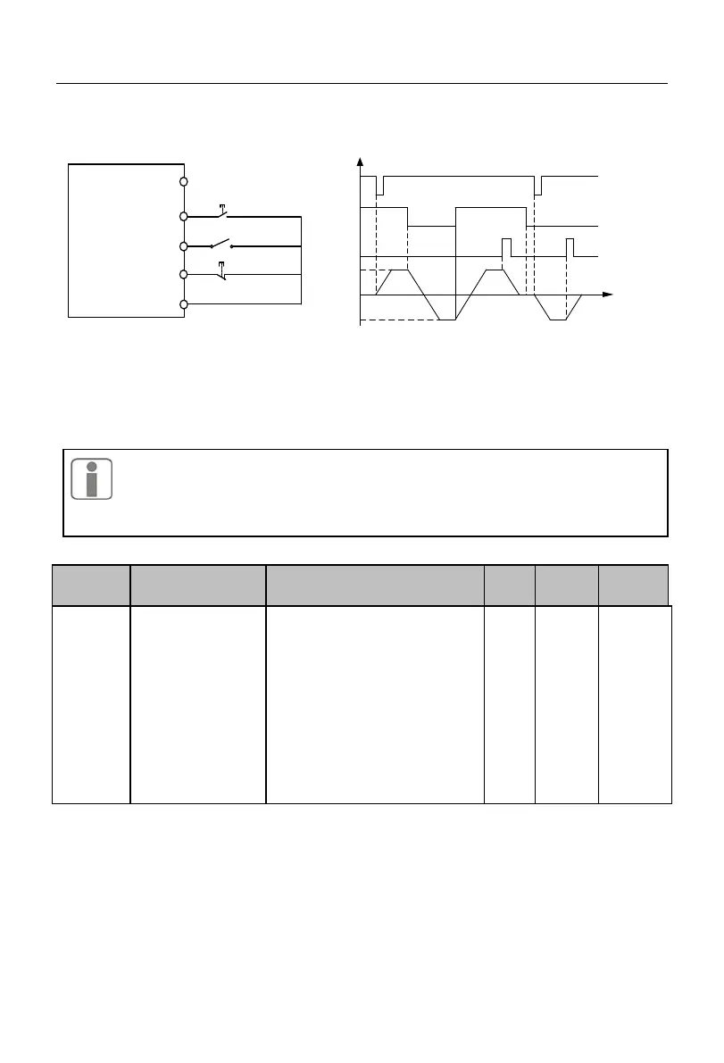
(c) Wiring diagram of two-line control
(F00.03=3)
(d) Forward/reverse running logic
(F04.19=0, F00.03=3)
Fig. 7-2 Three-line Control
The three-line control logic of the A90 series inverter is consistent with the
conventional electrical control. The keys and knob switches should be used
correctly as shown in the schematic diagram. Otherwise, operation errors may be
caused.
Options of main
frequency source A
0: digital frequency setting
F00.07
1: AI1
2: AI2
3: retention
4: VP (keyboard potentiometer)
5: retention
6: Percentage setting of main
frequency communication
7: Direct setting of main
frequency communication
8: retention
F00.04=0: digital frequency setting F00.07
The main frequency source A depends on the digital frequency setting F00.07.
F00.04=1:AI1
F00.04=2:AI2
F00.04=4:VP
 Loading...