User Manual of A90 Series Inverter
144
Positive/negati
ve logic 1 of
digital input
terminal
0: positive logic is valid in the closed
state/invalid in the open state
1: negative logic is valid in the closed
state/invalid in the open state
Positive/negat
ive logic 2 of
digital input
terminal
0: positive logic is valid in the closed
state/invalid in the open state
1: negative logic is valid in the closed
state/invalid in the open state
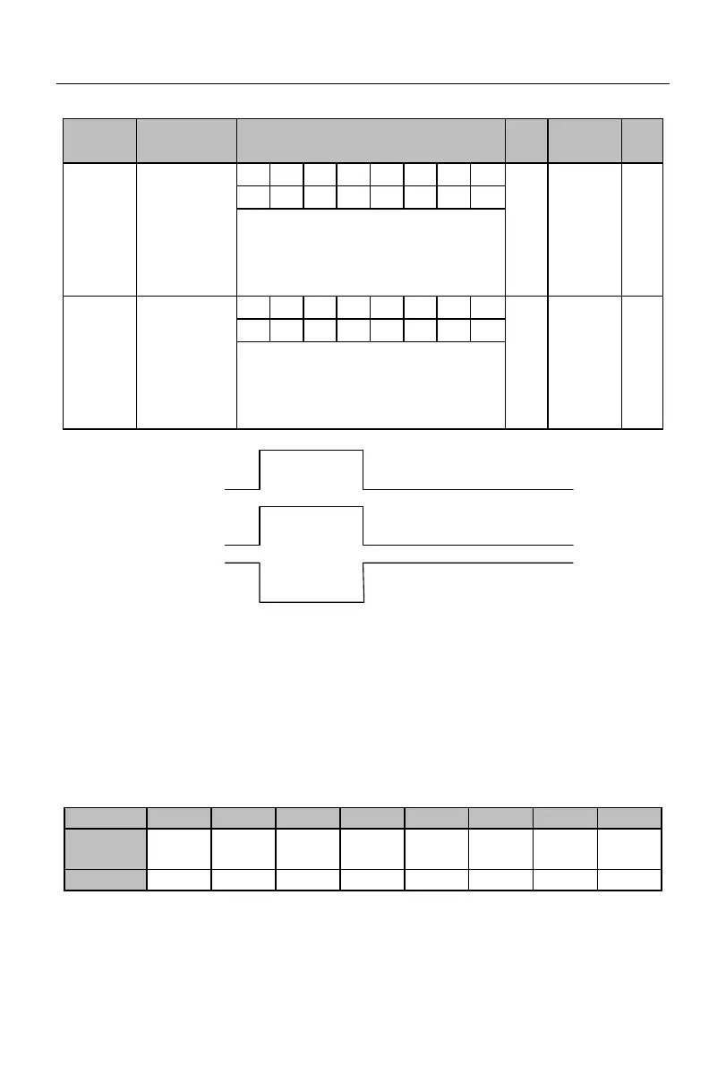
Xi input
Positive logic
sampling
Negative logic
sampling
Close
Valid
Invalid
Invalid
Valid
Off
Fig. 7-7 Schematic Diagram of Positive/Negative Logic Sampling of Terminal
When the bit is set to 0, the multi-function input terminal is valid in the closed status
and invalid in the open status;
When the bit is set to 1, the multi-function input terminal is valid in the open status
and invalid in the closed status.
These function code are subject to bit operation. You only need to set the
corresponding bit to 0 or 1. Take F02.15 as an example, as shown in the following table:
Table 7-5 Function Code Details of Bit Operation
The seventh bit is reserved and cannot be set. The specific displayed value does not
mean anything.
 Loading...