User Manual of A90 Series Inverter
147
digital input terminals. You only need to set the corresponding bit to 1. To use the AI2
terminal as a digital terminal, you only need to set F02.31=xx1x. The analog input and
digital logic conversion are as follows:
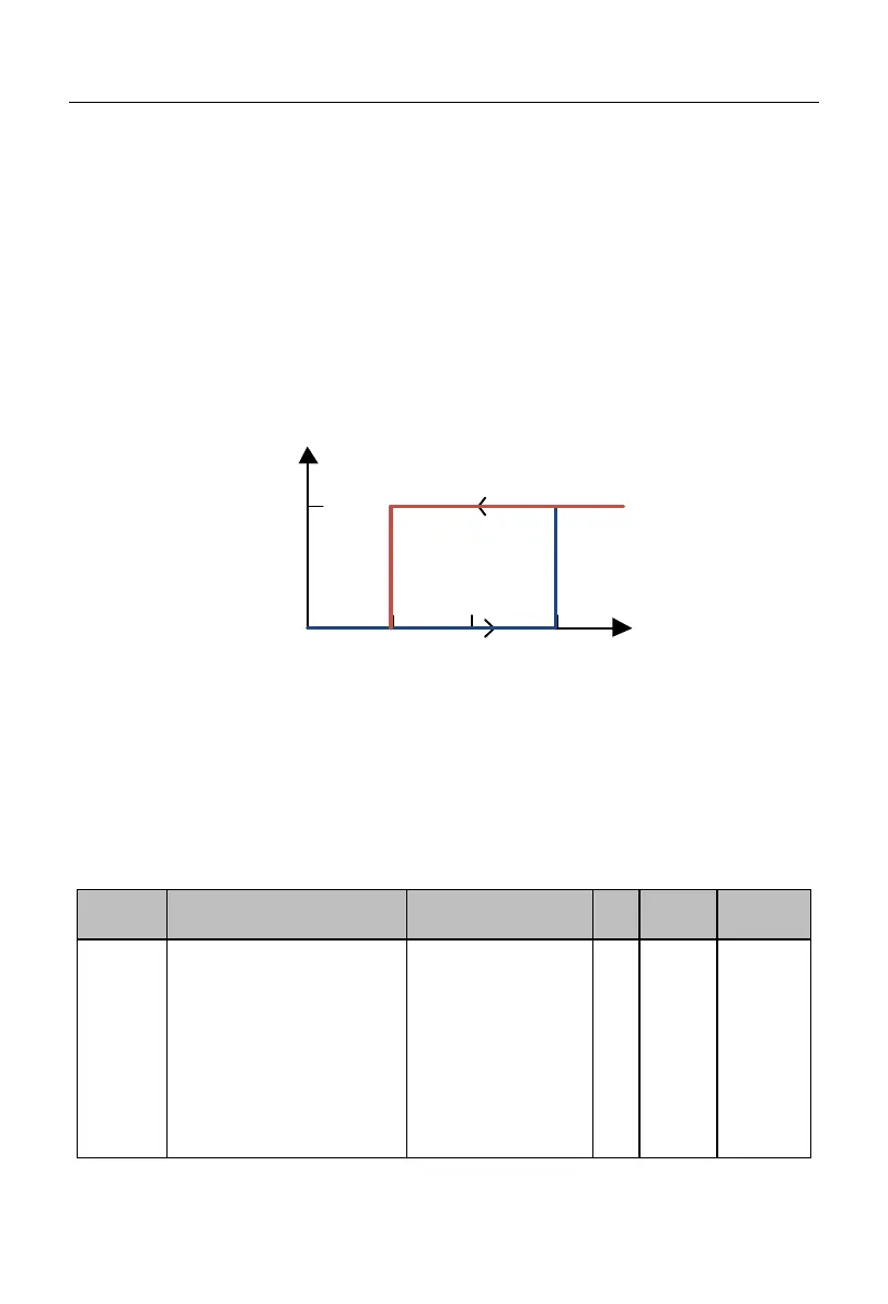
When the input voltage of the terminal is less than 1V, its corresponding logic
status will be invalid;
When the input voltage of the terminal is greater than 3V, its corresponding
logic status will be valid;
When the input voltage of the terminal is within [1V, 3V], its corresponding
logic status will remain unchanged.
Fig. 7-10 Correspondence between Analog Input Terminal Voltage and Current Logic
Status
If it is used as an analog input terminal, the filter time and corresponding offset curve
can be set via F02.32 to F02.60. The terminals AI1 to AI4 can be set separately.
Options of analog input
curve
Ones place:
Options
of AI1 curve
0: curve 1
1: curve 2
2: curve 3
3: curve 4
Tens place:
AI2 curve
selection
0: curve 1
 Loading...