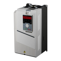
User Manual of A90 Series Inverter
160
Acceleration and
deceleration output
frequency
★
Fmax, maximum frequency (F00.16)
Ie, rated current of the inverter (F12.21)
Ue, rated voltage of the inverter (F12.20)
Pe, rated power of the inverter (F12.19)
The output physical quantity of the analog output terminal can be switched between
the voltage signal (0.00V to 10.00V) and current signal (0.00mA to 20.00mA) via the DIP
switch. For the voltage signal output, the value from 0.0% to 100.0% corresponds to the
output 0.00V to 10.00V. For the current signal output, the value from 0.0% to 100.0%
corresponds to the output 0.00mA to 20.00mA. For details, please see “0 Wiring of analog
output terminals”.
The above function codes are usually used to correct the zero drift of analog output
and the deviation of output amplitude. They can also be used to customize the required AO
output curve to meet the requirements of different instruments or others. If the offset is
represented by “b”, the gain by “k”, actual output by “Y” and standard output by “X”, the
actual output is: Y=kX+b.
1.
In order to meet the needs of different instruments or external devices, the
full-scale voltage of M1 and M2 is actually 10.9V and the full-scale current is
actually 22mA.
2.
M1 and M2 are set to 0.00-10.00V by default.
3.
Where there are high precision requirements for the analog output during operation,
test the no-load outputs of the terminals M1 and M2 with a multimeter first.
Control logic
options of PLC
output terminal
D7 D6 D5 D4 D3
D2 D1 D0
* * * * *

 Loading...


