User Manual of A90 Series Inverter
243
complete the aforesaid operations by setting the VX1 delay.
When F17.09=xxxxxxx1, the VX1 status depends on the bit 0 of the function
code F17.10.
The status of the virtual input terminal is directly dependent on the function code.
This is mainly used for remote control by the host. The remote control terminal can
be used to enable and disable the input terminal status directly with the function code
0x41 by changing the value of F17.10 through communication.
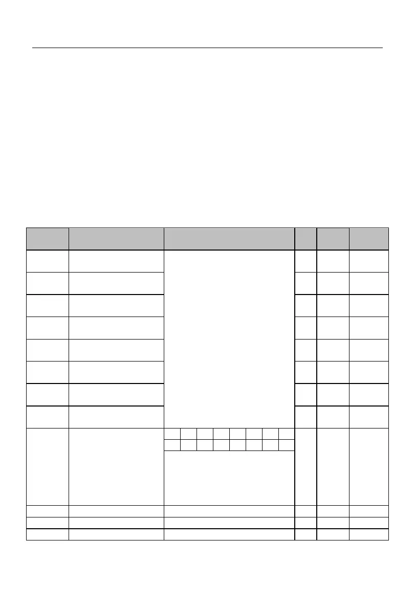
The standard A90 series inverter is equipped with eight virtual multi-function output
terminals (VY1 to VY8), and their functions and usages are essentially the same as those of
the actual output terminals. Differences are described below. For their similarities, refer to
the parameter description of the digital output terminal function options of the F03 group.
VY1 virtual output
function options
The same as the digital output
terminal function options of the
F03 group, as detailed in Table
7-6 Function List of
Multi-function Digital Output
Terminals
VY2 virtual output
function options
VY3 virtual output
function options
VY4 virtual output
function options
VY5 virtual output
function options
VY6 virtual output
function options
VY7 virtual output
function options
VY8 virtual output
function options
Virtual output
positive/negative logic
0: positive logic, valid in the
closed state/invalid in the open
state
1: Negative logic, invalid in the
closed state/valid in the open state
 Loading...