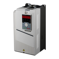
User Manual of A90 Series Inverter
262
9.2.5 Electromagnetic interference and RF interference
Since the inverter works in the high-frequency switching status, electromagnetic
interference and RF interference will be generate to the control device. The following
measures can be taken.
Reduce the carrier frequency (F00.23) of the inverter.
Install a noise filter on the input side of the inverter.
Install a noise filter on the output side of the inverter.
Install a metal tube outside the cables. Install the inverter in a metal casing.
Make the inverter and motor grounded reliably.
Connect the main circuit and control circuit separately. Use the shielded cables in
the control circuit, and connect them according to the wiring method in Chapter3.
9.2.6 Action of leakage circuit breaker
When the inverter is running, the leakage circuit breaker works.
Since the inverter outputs high-frequency PWM signals, a high-frequency leakage
current will be generated. Please use the dedicated leakage circuit breaker with the current
sensitivity above 30mA. If an ordinary leakage circuit breaker is used, use a leakage circuit
breaker with the current sensitivity above 200mA and action time of more than 0.1s.
9.2.7 Mechanical vibration
The inherent frequency of the mechanical system resonates with the carrier frequency
of the inverter.
The motor is not faulty, but the mechanical system produces sharp resonant sounds.
This is caused by the resonation between the inherent frequency of the mechanical system
and carrier frequency of the inverter. Please adjust the carrier frequency (F00.23) to avoid
resonation.
The inherent frequency of the mechanical system resonates with the output frequency
of the inverter.
Resonation between the inherent frequency of the mechanical system and output
frequency of the inverter will lead to mechanical noise. Please use the vibration suppression
function (F05.13), or install the anti-vibration rubber or take other anti-vibration measures
on the motor base.
PID control oscillation

 Loading...


