User Manual of A90 Series Inverter
45
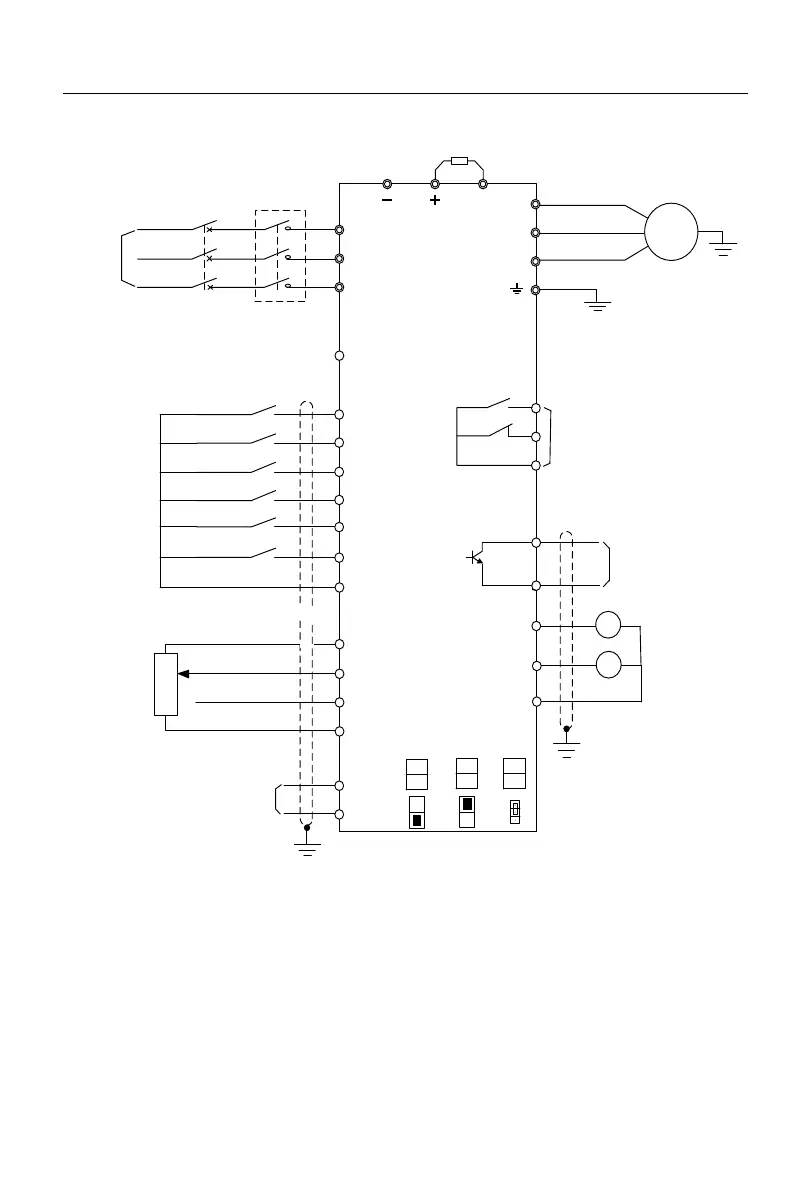
3.3.10
Standard Wiring Diagram of Control Circuit
Grounding
Fault resetting
Multi-segment
speed terminal 3
Multi-segment
speed terminal 2
Multi-segment
speed terminal 1
Forward/Reverse
Operation
PB
Braking resistor
Communication
interface
Grounding
A
-
A+
GND
Multi-function input
terminal
MC
S/L2
T/L3
R/L1
Inverter
Open collector
output
24V/50mA
EC
EB
X1
X2
Y1
X5
X4
X6
X3
Relay output contact
EA
Grounding
Multi-function
analog output
AI2
AI1
GND
MCCB
Power
supply
Frequency
setting
potentiometer
AC250V, more than 10mA, less than 3A
DC30V, more than 10mA, less than 1A
COM
COM
W
V
U
3
2
1
1kΩ~5kΩ
0-10V
0-10V/0-20mA
24V output
100mA
10V
24V-COM
+10V/20mA
V/I
M2
V
AI2
I
S2
OFF
485
ON
S1
M
1
R1
V
M1
V
I
M2
J7
Fig. 3-18 Standard Wiring Diagram of Control Circuit
For the A90-4T017B model and below, the terminals COM and GND are connected
internally.
It is recommended to use the wires with a diameter of 0.5-1mm
2
in the control circuit.
Install the control circuit terminals with the PH0 Phillips screwdriver. The tightening
 Loading...