EM330D User Manual
A Special Purpose Inverter for Hoisting
75
inverter is running, and acceleration/deceleration time can be changed immediately. See
Table 7-3 for the programming mode of acceleration/deceleration time terminal 1 and 2.
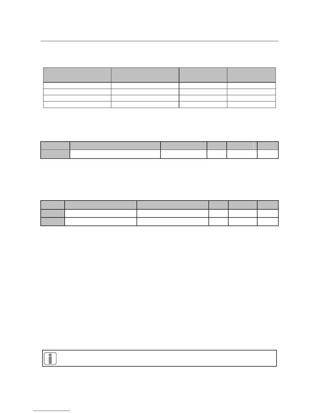
Table 7-2 Programming mode of acceleration/deceleration time terminals
Acceleration/Deceleration
Time Terminal 1
Acceleration/Deceleration
Time Terminal 2
As shown in Table 7-2, acceleration/deceleration time refers to acceleration time 1 and
deceleration time 1 in regular operation mode (without using acceleration/deceleration
terminal).
Acceleration/Deceleration Time Unit
F3-21=0The unit of acceleration/deceleration time is second. The acceleration/deceleration
time can be set continuously in the range of 0.00~600.00 seconds.
F3-21=1The unit of acceleration/deceleration time is minute. The acceleration/deceleration
time is can be set continuously in the range of 0.00~600.00 minutes.
DC Brake Propotion at Start
Before inverter starts, the motor may run in low speed. If inverter starts immediately at
mean time, overcurrent may occur. In order to avoid such faults, start DC brake to stop
motor before inverter starts, and then the inverter runs to setting frequency as per setting
direction.
F3-22 Different setting values can define different start DC brake torques.
When the parameter≤30.00, the percentage base is the rated output voltage of
inverter. While, the DC brake controls the DC voltage generated by motor
windings.
When the parameter≥30.01, the percentage base is the rated output current of
inverter of Model G. While, the DC brake controls the DC current generated by
motor windings.
F3-23 Set the DC brake time at start. Inverter runs immediately when the time is up.
If F3-23=0.00, DC brake is disabled at start.
The DC brake process at start is as shown in Figure 7-8.
The function is applied to that one inverter drives multi-motors.
 Loading...

