EM330D User Manual
A Special Purpose Inverter for Hoisting
86
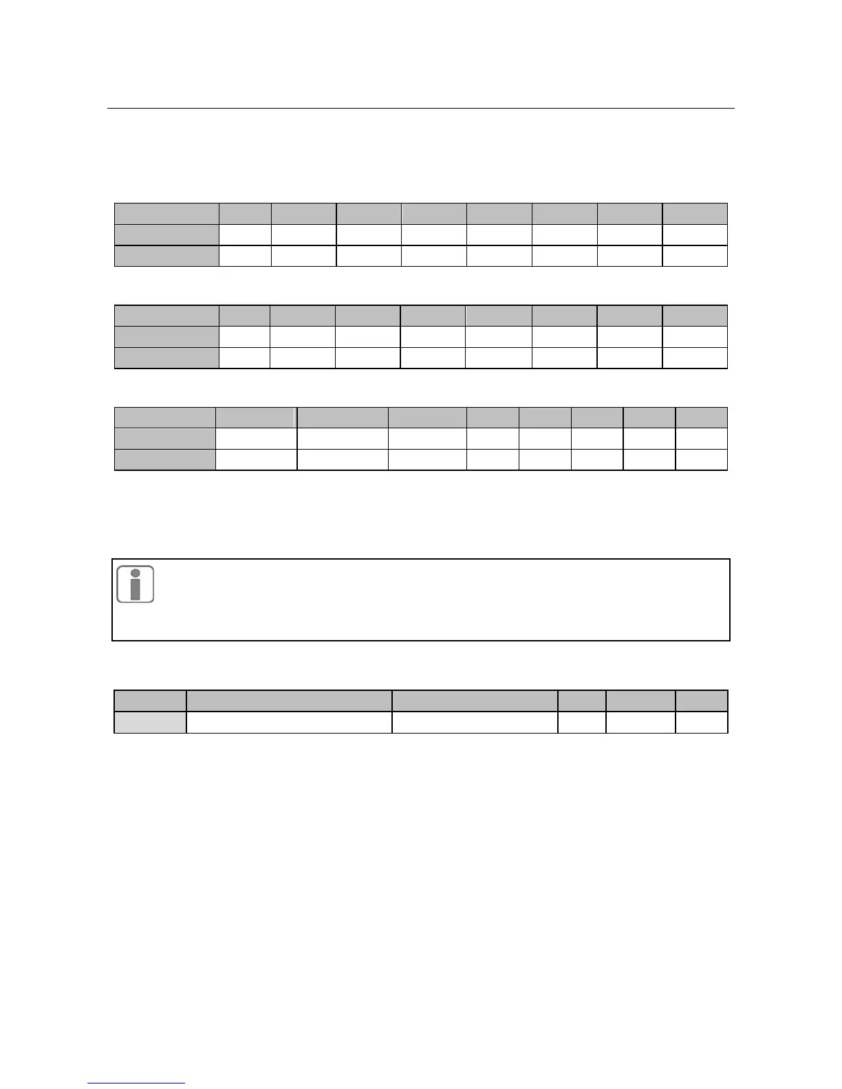
FC-28, FC-29, and FC-30 are in bit operation. Set the bits corresponding to the trips as 0
or 1.As shown in the following tables:
FC-28 Disabled Trips 1:
For example, set Bit 6=1(Corresponding to ILP) to disable ILP trip, FC-28=01000000.
Set Bit 1=1(Corresponding to OLP) to disable OLP trip, and set Bit 6=1(Corresponding to
EST) to disable EST trip, FC-29=01000010.
1.Unless required, please do not disable any trip in case any damage occurred
when inverter would not trip at faults.
2. Ol1 is motor overload, but displayed as Ol. Generally, motor overload is longer
than inverter overload, so it is unnecessary to adjust the relevant settings.
Programmable Input/Output Terminal Options
Numeric Input Filter Times
Because input terminal adapts level triggered mode or pulse triggered mode, when inverter
is reading terminal status, the multi-function input terminal signals have to be processed by
digital filtering in order to avoid interference.
FE-00 does not need to be adjusted on general conditions. When adjustment is
required, please note the relations between filter times and lasting time when
terminal is on. It is to avoid that inverter is ease to be interfered due to
insufficient filter times, or slow response or command loss due to too many filter
times.
 Loading...

