From the library of Superior Sewing Machine & Supply LLC - www.supsew.com
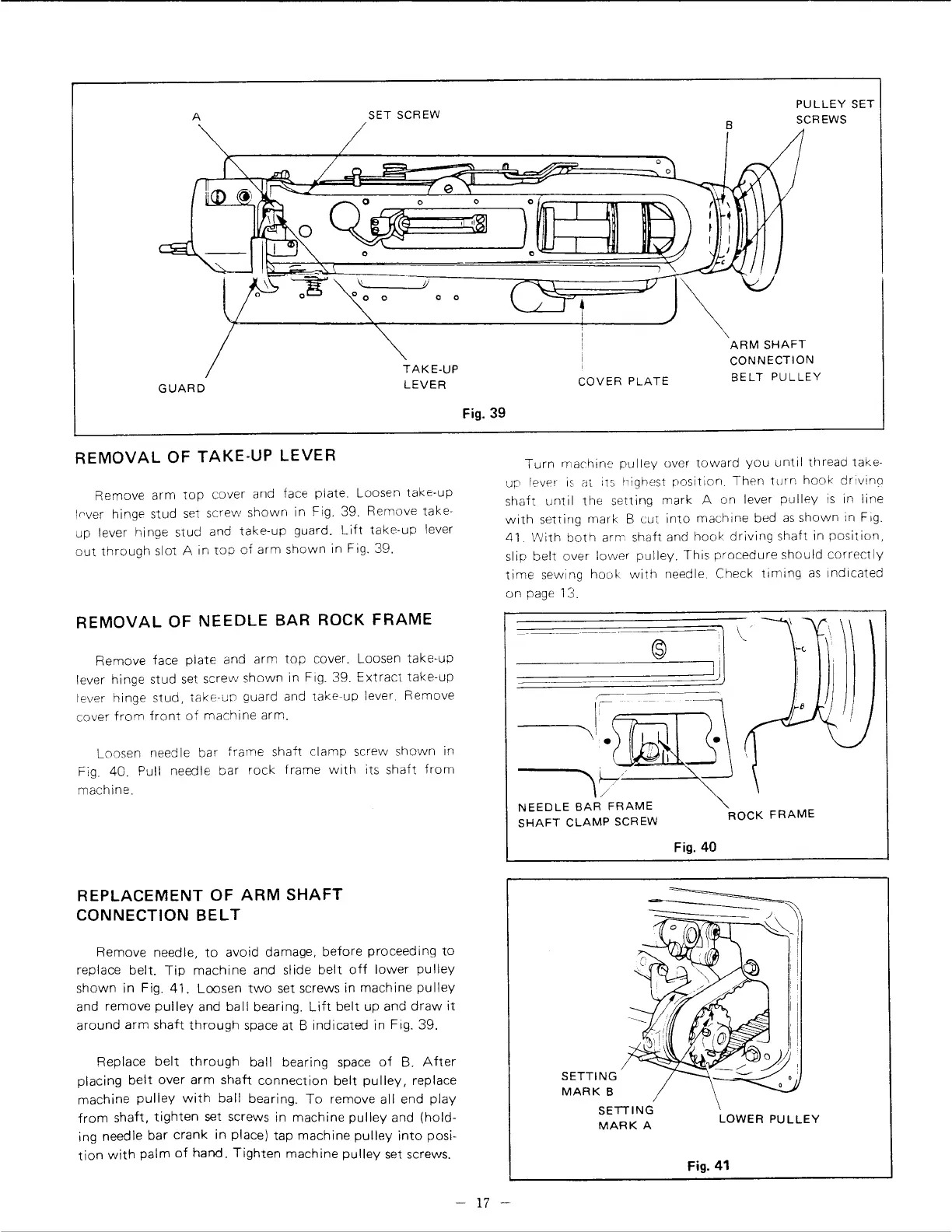
A
SET SCREW
B
PULLEY
SET
SCREWS
~~~~;~-=---=---=-~~~====~~~~~~~~\...-.;:;.,.-
"J'c--::-.--------"=====~~=~~=
~
GUARD
REMOVAL
OF TAKE-UP LEVER
TAKE-UP
LEVER
Remove
arm
top
cover and face plate. Loosen
take-up
lrver
hinge stud
set
screw
shown
in
Fig_
39. Remove take-
up lever hinge stud and
take-up
guard.
Lift
take-up
lever
out
through
slot A in
top
of
arm
shown
in Fig. 39.
REMOVAL
OF
NEEDLE
BAR ROCK FRAME
Remove face
plate
and
arm
top
cover. Loosen
take-up
lever hinge stud
set
screw
shown
in Fig. 39.
Extract
take-up
lever hinge
stud,
take-up
guard and
take-up
lever_
Remove
cover
from
front
of
machine
arm.
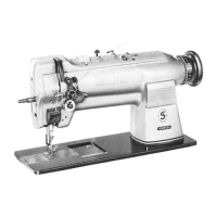
Loosen needle bar
frame
shaft
clamp
screw
shown
in
Fig_
40_
Pull needle
bar
rock
frame
with
its
shaft
from
machine.
REPLACEMENT OF
ARM
SHAFT
CONNECTION
BELT
Remove needle,
to
avoid damage,
before
proceeding
to
replace
belt.
Tip
machine
and slide
belt
off
lower
pulley
shown
in
Fig.
41.
Loosen
two
set screws in
machine
pulley
and remove
pulley
and ba
11
bearing_
Lift
belt
up and
draw
it
around
arm
shaft
through
space at B indicated in Fig. 39.
Replace
belt
through
ball bearing space
of
B.
After
placing
belt
over
arm
shaft
connection
belt
pulley,
replace
machine
pulley
with
ball
bearing.
To
remove all end
play
from
shaft,
tighten
set screws in
machine
pulley
and
(hold-
ing needle
bar
crank
in
place) tap
machine
pulley
into
posi-
tion
with
palm
of
hand.
Tighten
machine
pulley
set screws.
COVER
PLATE
Fig.
39
ARM
SHAFT
CONNECTION
BELT
PULLEY
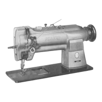
Turn
machine
pulley
over
toward
you
until
thread take-
ur
levPr
is
at its !1ighest position_
Then
turn
hook
drivino
shaft
until
the
setting
mark
A on lever
pulley
is
in
line
with
setting
mark
B cut
into
machine
bed
as
shown
in Fig.
41. VVith
both
arm
shaft and
hook
driving
shaft in
position,
slip
belt
over
lower
pulley.
This
procedure
should
correctly
time
sewing hooh:
with
needle_ Check
timing
as
indicated
on page
13.
------1
.
•
,7
NEEDLE
BAR
FRAME
SHAFT
CLAMP
SCREW
SETTING
MARK
B
SETTING
MARK
A
ROCK
FRAME
Fig.
40
LOWER
PULLEY
Fig.
41
-
17
-