n
FEED
ECCENTRIC
AND
FEED-LIFTING
ECCENTRI
m
FEED
ECCENTRIC
LATER
CONNECTING
ROD
1
SOONER
KEEP
GEARS
IN
MESH
AT
ALL
TIMES
THREE
FEED
ECCENTRIC
SCREWS
FEED-LIFTING
ECCENTRIC
THREE
FEED-LIFTING
ECCENTRIC
SCREWS
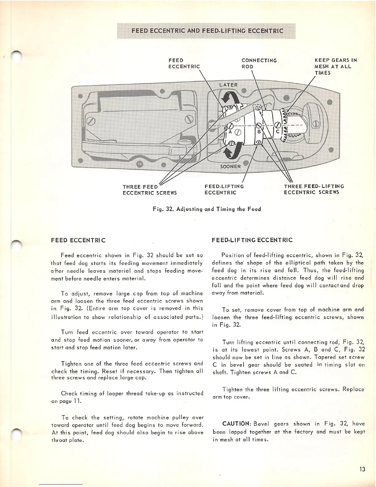
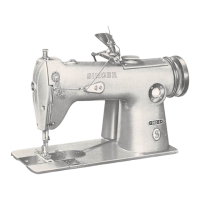
Fig.
32.
Adjusting
and
Timing
the
Feed
FEED
ECCENTRIC
Feed
eccentric
shown in
Fig.
32
should
be
set
so
that
feed dog
starts
its feeding movement immediately
after
needle
leaves
material
and
stops
feeding move
ment
before
needle
enters
material.
To adjust, remove large cap
from
top of machine
arm
and
loosen
the
three
feed
eccentric
screws
shown
in Fig. 32. (Entire arm top cover is removed in
this
illustration
to show
relationship
of
associated
ports.)
Turn feed
eccentric
over
toward
operator
to
start
and
stop
feed motion
sooner,
or
away
from
operator
to
start
and
stop
feed motion
later.
Tighten one of the three feed
eccentric
screws
and
check
the timing.
Reset
if
necessary.
Then tighten all
three
screws
and
replace
large
cap.
Check
timing of looper thread
take-up
as
instructed
on
page
11.
To
check
the
setting,
rotate machine pulley over
toward operator until feed dog begins to move forward.
At
this
point, feed dog should
also
begin to
rise
above
throat
plate.
FEED-LIFTING
ECCENTRIC
Position
of
feed-lifting
eccentric,
shown in
Fig.
32,
defines
the
shape
of
the
elliptical
path
taken
by
the
feed
dog in its
rise
and fall.
Thus,
the feed-lifting
eccentric
determines
distance
feed dog will
rise
and
fall
and
the
point where
feed
dog will
contact
and
drop
away
from
material.
To
set,
remove
cover
from
top
of
machine
arm and
loosen the three feed-lifting
eccentric
screws,
shown
in
Fig.
32.
Turn lifting
eccentric
until connecting rod. Fig. 32,
is
at
its
lowest point. Screws A, B and C,
Fig.
32
should
now be
set
in
line
as
shown.
Tapered
set
screw
C in bevel
gear
should be
seated
in timing
slot
on
shaft.
Tighten
screws
A and C.
Tighten
the
three lifting
eccentric
screws.
Replace
arm
top
cover.
CAUTION: Bevel
gears
shown in
Fig.
32, have
been lapped together
at
the
factory and must be kept
in
mesh
at
all
times.
13