NEEDLE
BAR
HEIGHT
Set looper at gauge distance
from
needle and time
looper, as instructed on page 9.
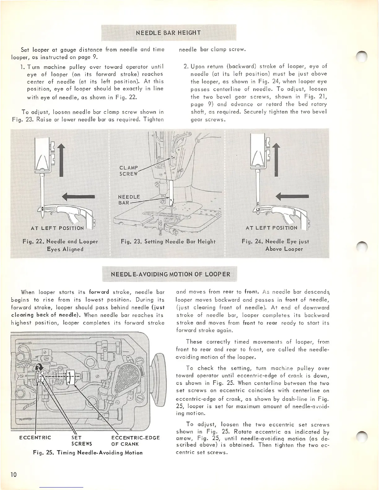
l.Turn
machine pulley over toward operator until
eye of looper (on its
forward
stroke) reaches
center
of
needle
(at
its
left position). At
this
position, eye of looper should be exactly in line
with
eye
of
needle,
as
shown in
Fig.
22.
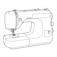
To
adjust,
loosen
needle
bar clamp
screw
shown in
Fig. 23. Raise or lower needle bar as required. Tighten
AT
LEFT
POSITION
CLAMP
SCREW
needle
bar clamp
screw.
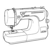
2. Upon return (backward) stroke of looper, eye of
needle
(at
its
left position) must be
just
above
the
looper,
as
shown in Fig. 24, when looper
eye
passes
centerline of needle. To adjust, loosen
the
two bevel gear screws, shown in Fig. 21,
page
9) and
advance
or retard
the
bed rotary
shaft,
as
required. Securely tighten the two bevel
gear
screws.
AT
LEFT
POSITION
Fig.
22.
Needle
and
Looper
Eyes
Aligned
Fig.
23.
Setting
Needle
Bar
Height
Fig.
24.
Needle
Eye
just
Above
Looper
NEEDLE-AVOIDING
MOTION
OF
LOOPER
When looper
starts
its
forward
stroke,
needle
bar
begins
to
rise
from
its
lowest
position.
During
its
forward
stroke,
looper should
pass
behind
needle
(just
clearing
back
of
needle).
When
needle
bar
reaches
its
highest
position, looper completes
its
forward
stroke
ECCENTRIC
SET
SCREWS
ECCENTRIC-EDGE
OF
CRANK
Fig.
25.
Timing
Needle-Avoiding
Motion
10
and moves
from
rear to front. As needle bar descend^
looper moves backward and
passes
in front of
needle,
(just
clearing
front of
needle).
At end of downward
stroke
of
needle
bar, looper
completes
its
backward
stroke and moves
from
front to rear ready to start its
forward stroke again.
These
correctly
timed movements of looper, from
front to
rear
and
rear
to front,
are
called
the
needle-
avoiding motion of the looper.
To check
the
setting,
turn machine pulley over
toward operator until
eccentric-edge
of crank is down,
as
shown in
Fig.
25. When
centerline
between
the
two
set
screws
on
eccentric
coincides
with
centerline
on
eccentric-edge
of crank,
as
shown by
dosh-line
in Fig.
25,
looper is
set
for maximum amount of
needle-avoid
ing
motion.
To
adjust,
loosen
the
two
eccentric
set
screws
shown in Fig. 25. Rotate eccentric
as
indicoted by
arrow.
Fig.
25, until
needle-ovoidinq
motion
(as
de
scribed above) is obtained. Then tighten the two ec
centric
set
screws.