3-12 Quick guide for installation and use - Strider Transmitter Link
Strider Link Series
SRFStrider-161004A-REV.A
Sinteck Sistemas Eletrônicos Ltda.
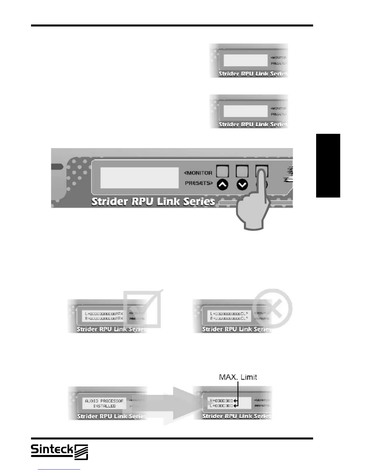
CHANNELS LEFT&RIGHT MENU
ATTENTION: This menu only works when is installed the
STEREO GENERATOR CARD and the “MPX
SELECTION” is selected to “INT” (See this menu in the
next pages).
The input levels of the left and right channels are
represented by vertical bars as indicated in the following
illustration.
The level is measured in percents when 100%
corresponds to a deviation of 100kHz of carrier.
3
The Strider Transmitter Link support the deviation of 100kHz without any kind of distortion.
“MAX” in the LCD corresponds to 110% of modulation, 110kHz of deviation. In some case, is
possible to transmit 110% of modulation, but note that in others channels must not have any
other users. The “CLP” corresponds to “CLIPPER”.
REMARK: NEVER let the transmitter modules more than “MAX” in any case.
L~ÛÛÛÛÛÛÛ
R~ÛÛÛÛÛ
STEREO GENERATOR
INSTALLED
MPX SELECTION
~INT. EXT.
When installed the AUDIO PROCESSOR CARD the maximum modulation will be 75%. If
this card is disabled, then the modulation level can pass of this limit like shows the
illustration.
03/P/31
 Loading...